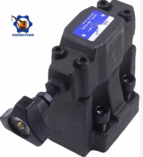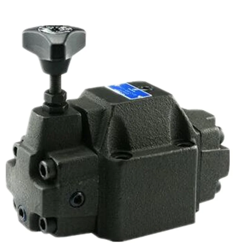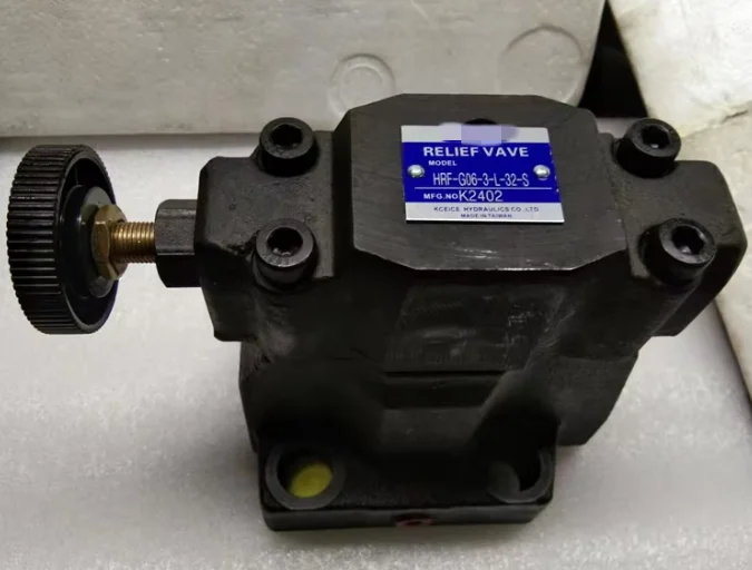


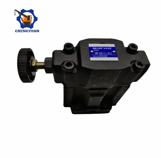


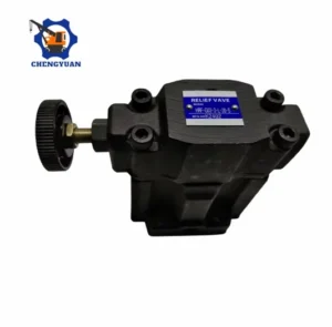
The Northman HRF Series (specifically including the HRF-G03-1-L32, HRF-G06, and HRF-G10-R32 entire dimension platform) of low noise pilot-operated subplate-mounted hydraulic relief valves manufactured by Chengyuan Hydraulic are premium fluid pressure management components engineered to fully cross-reference the stringent sound-level and flow stability limits of Northman Fluid Power. Engineered explicitly for applications where minimizing acoustic feedback is a critical environmental or performance mandate, this series limits dynamic fluid ripple by leveraging fluid differential pressure across a micro-drilled balance piston orifice matrix. Covering all primary subplate port patterns—including the heavy G03 (3/8″), G06 (3/4″), and G10 (1-1/4″) footprints—Chengyuan applies precise CNC labyrinth pathway machining and vacuum case-hardened seat lapping to offer 100% original-place interchangeable plug-and-play compatibility for standard ISO 6264 interfaces. Prior to dispatch, every individual relief assembly undergoes 100% simulated continuous high-load hot thermal auditing, step-response stability analysis, and localized decibel emission validation, ensuring a reliable safeguard against circuit over-pressurization without high-frequency fluid humming.
Technical Specifications :
Brand Compatibility Matrix: Northman HRF / Yuken Standard Low Noise Series Equivalent
Target Part Number Nomenclature Covered: HRF-G03-1-L32, HRF-G06-3-L-32, HRF-G10-R32 Series
Physical Mounting Geometry: Standard Subplate Plate Type (ISO standard layout configuration)
Maximum Allowable Continuous Operating Pressure: Rated parameters up to 210 bar to 250 bar (21 – 25 MPa / Up to 3625 PSI)
Maximum Volumetric Flow Group Capacity:
HRF-G03 Frame Size (NG10 / 3/8″ Porting): Delivering up to 100 L/min (26.4 GPM)
HRF-G06 Frame Size (NG25 / 3/4″ Porting): Delivering up to 250 L/min (66.0 GPM)
HRF-G10 Frame Size (NG32 / 1-1/4″ Porting): Delivering up to 400 L/min (105.6 GPM)
Pressure Regulation Stage Indexes (Code 1 / 2 / 3 Matrix):
Pressure Code 1 Configuration: Adjustable range spanning 7 to 70 $kgf/cm^2$ (0.7 – 7.0 MPa / Optimized for injection plastic back-pressure circuits)
Pressure Code 2 Configuration: Adjustable range spanning 35 to 140 $kgf/cm^2$ (3.5 – 14.0 MPa)
Pressure Code 3 Configuration: Heavy system master relief setup spanning 70 to 250 $kgf/cm^2$ (7.0 – 25.0 MPa)
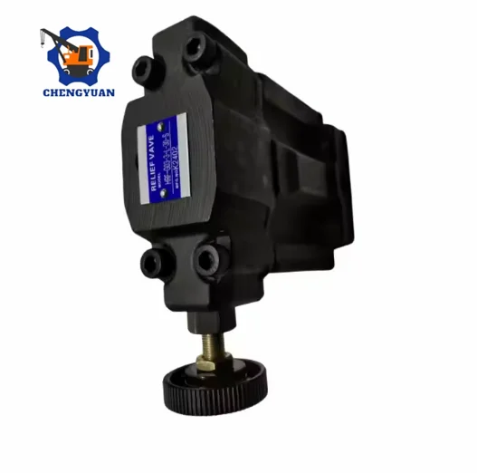
Adjustment Knob Mechanical Direction Suffix (L32 / R32 Matrix):
L Suffix (Left Layout): Adjuster assembly situated on the left hand side when facing the secondary T tank pathway
R Suffix (Right Layout): Adjuster assembly situated on the right hand side when facing the primary P pressure pathway
Series Design Code 32: Revamped internal orifice structure optimization for modernized hydraulic oil formulations
Cavity Interface Standards Matching: ISO 6264-AR-06-02 (G03), ISO 6264-AS-08-02 (G06), ISO 6264-AT-10-02 (G10)
Key Technical Advantages:
CFD-Modeled Internal Acoustic Labyrinth Fluid Path: The foundational distinction of the HRF package lies in its multi-layered fluid channel design. The inner exhaust core and the base region of the main balancing valve are machined with dynamic anti-turbulence curves shaped via computational fluid dynamics. This configuration absorbs localized energy during extreme high-to-low pressure drop transformations, suppressing structural cavitation and delivering a major 6-10 dB(A) reduction in acoustic emissions compared to conventional architectures.
Dual-Staged Internal Damping Balance Piston Assembly: The internal primary sliding spool incorporates a lightweight, high-yield alloy balanced piston structure. A micro-precision laser-drilled internal orifice channels transient system fluid shocks between opposing piston cavities. This restriction forms a reliable hydraulic damper that effectively eliminates high-frequency mechanical slide chattering, maintaining a uniform circuit response during severe multi-pump pressure waves.
Vacuum-Quenched Alloy Seating Faces with Low-Drift Threshold Performance: The downstream pilot stage features premium chromium bearing steel poppets that undergo an advanced vacuum nitrogen hardening treatment. This process provides highly resilient seating contours capable of enduring continuous high-velocity oil bypass without eroding. Heavy-duty internal calibration springs are pre-stressed to prevent physical relaxation, guaranteeing consistent cracking-pressure accuracy across millions of cycles.
Monoblock High-Density Anti-Breathing Iron Substrate Housing: The complete external manifold-mount cast body is molded from high-tensile, close-grain structural casting iron. Tested to resist cross-sectional fatigue expansion at 250 bar continuous alternating loading, the inner housing maintains micro-inch geometrical clearances under varied operating oil temperatures.
Application Areas:
Precision Plastics Injection Molding Machinery: Main back-pressure regulation and screw charging control manifolds for heavy-duty plastic injection systems (predominantly deploying the HRF-G03-1 and HRF-G06-1 configurations).
Enclosed Plant Floor Automated Central Hydraulic Sub-Stations: High-efficiency pressure control for multi-axis automotive press lines, CNC stamping cells, and industrial workstations constrained by strict indoor OSHA-level decibel limitations.
Heavy Steel Slitting and Metal Baling Equipment: Main system structural system overload protection and safety unloading bypass circuits handling sudden cylinder reversals.
Expert Maintenance Tips:
Never Forcefully Turn the Pressure Regulator Suffix Screw Past its Internal Unloaded Stops: When adjusting low-range back-pressure configurations such as the HRF-G03-1-L32, always rotate the handknob counter-clockwise smoothly and cease immediately when the spring tension vanishes. Forcing the screw past its structural limits under active return line pressure spikes can dislodge internal backup hardware, resulting in sudden external fluid escape.
Apply High-Viscosity Grease to Retain Subplate O-Rings During Symmetrical Multi-Stage Torquing: Because the HRF-G03, G06, and G10 are strictly subplate plate-mounted components, ensure all sealing elastomer rings are securely seated into their designated grooves with high-viscosity media before positioning the assembly. Always cross-tighten the mounting bolts in a 3-stage incremental torque sequence. Uneven clamping forces can pinch or shear the O-rings, leading to microscopic leaks underneath the valve body.
Keep the Remote Vent Port Securely Blinded with Factory Plugs When Not Linked to a Secondary Valve: Every HRF series faceplate features a dedicated Rc 1/4 or 1/8 remote control vent pathway. For basic single-stage onboard manual control loops, this vent port must be sealed using a high-tensile thread plug. If this plug backs out or develops a weep, the main pilot chamber will depressurize completely, resulting in a sudden, un-diagnostic collapse of circuit operating pressure.