What Is a Hydraulic Vane Motor?
How Does a Hydraulic Vane Motor Work?
The working cycle is simple:
- Hydraulic oil enters the inlet port.
- Oil pressure acts on the vanes.
- The vanes slide in rotor slots and follow the cam ring contour.
- The pressure difference between inlet and outlet creates torque.
- The shaft rotates and transmits mechanical power.
- Return oil exits through the outlet port.
The two key sizing relationships are:
1.Torque ≈ ΔP × displacement × mechanical efficiency / 2π
2.Speed ≈ flow rate × volumetric efficiency/displacement
For a real selection, use the manufacturer’s performance curves, not only theoretical formulas. Catalog data can vary by displacement, oil viscosity, pressure, speed, drain type, and shaft configuration. Parker’s M3/M4 catalog, for example, lists displacements from about 18.5 to 222 cm3/rev and provides torque and power data at defined pressure and speed conditions. (parker.com)
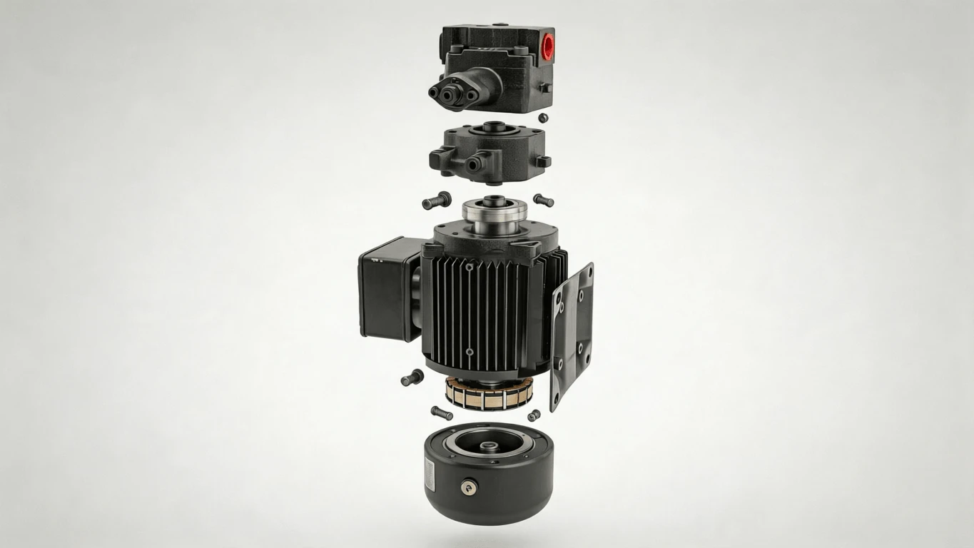
Main Components of Hydraulic Vane Motors

| Component | Function |
|---|---|
Rotor |
Carries the vanes and drives the shaft |
Vanes |
Slide in rotor slots and form moving sealing chambers |
Cam ring |
Defines the eccentric working path and displacement |
Port plates |
Direct oil into and out of the working chambers |
Shaft and bearings |
Transmit torque and support external loads |
Seals and case drain |
Control leakage and protect shaft seals |
Shuttle/check valves |
Used in some designs for pressure balancing and protection |
Advantages of Hydraulic Vane Motors
Hydraulic vane motors are valued for smooth rotation, low torque ripple, compact power density, and good starting torque. Parker’s M5 vane motor catalog highlights low noise, low torque ripple, pressure-balanced construction, and heavy-duty use cases such as mixers, shredders, compressor drives, generator drives, and fan drives. (parker.com)
Main advantages include:
- Smooth operation at medium and high speeds
- Good starting torque compared with many simple motor types
- Compact size for the power output
- Reversible rotation in suitable bi-directional designs
- Useful high-flow capability in medium-pressure systems
- Lower noise and torque ripple in well-designed units
Disadvantages and Limitations
A vane motor is not always the best choice. It needs clean oil, correct viscosity, controlled pressure spikes, and proper drain-line design. Parker’s troubleshooting guide links poor viscosity, unsuitable fluids, contamination, and aeration with lubrication failure, overheating, corrosion, and premature breakdown.
Common limitations include:
- More sensitive to contamination than rugged low-cost gear motors
- Generally not as efficient as premium piston motors at high pressure
- Case drain and back pressure limits must be respected
- Very low-speed operation may need special review
- Pressure spikes can crack or rupture internal components
- Shaft misalignment and radial loads can shorten bearing and shaft life
Industrial Applications
Hydraulic Vane Motor vs Gear Motor vs Piston Motor
| Motor type | Best fit | Strength | Limitation |
|---|---|---|---|
Gear motor |
Cost-sensitive medium-duty systems |
Simple, rugged, economical |
More ripple, lower refinement |
Vane motor |
Smooth medium-pressure/high-flow systems |
Smooth speed, compact, good starting torque |
Needs cleaner oil and proper drain control |
Piston motor |
High-pressure/high-efficiency systems |
High efficiency and pressure capability |
Higher cost and complexity |
How to Select a Hydraulic Vane Motor
Start with the load, not the catalog part number.
- Define required torque at start, run, and stall.
- Confirm available pressure drop across the motor.
- Calculate the required displacement.
- Check target speed against available pump flow.
- Verify continuous and intermittent pressure ratings.
- Confirm drain type, drain pressure, and return-line conditions.
- Check shaft type, mounting flange, port standard, and allowable radial/axial load.
- Review oil viscosity, fluid type, filtration, and operating temperature.
- Use manufacturer curves for final torque, speed, leakage, and power validation.
For example, Parker’s M3/M4 data shows some models operating up to 230 bar and 4000 rpm depending on size and fluid condition, but those limits are model-specific. The same catalog also gives strict low-pressure port limits for external and internal drain versions.
Common Problems and Troubleshooting
| Table Header | Table Header | Table Header |
|---|---|---|
Low speed |
Insufficient pump flow, internal leakage, high load |
Flow test, leakage, valve settings |
Low torque |
Low pressure drop, worn vanes, pressure relief opening |
Inlet pressure, outlet pressure, ΔP |
Noise or vibration |
Cavitation, aeration, bearing damage, misalignment |
Inlet condition, oil level, shaft coupling |
External leakage |
Shaft seal wear, excessive case pressure, seal damage |
Drain line, seal condition, back pressure |
Overheating |
Excessive leakage, wrong viscosity, pressure losses |
Oil temperature, viscosity, filtration |
Shaft failure |
Misalignment, overhung load, torque spikes |
Coupling fit, load path, pressure transients |
- ISO 4413:2010 hydraulic fluid power safety requirements
- National Fluid Power Association
- Parker Industrial Hydraulics technical literature
- Yuken Basic Hydraulics and Components