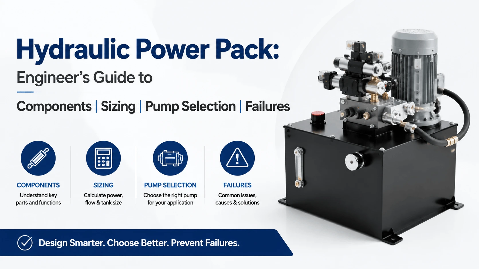
Hydraulic Power Pack: Engineer’s Guide

Hydraulic Power Pack- Engineer's Guide to Components, Sizing, Pump Selection & Failures

Table of Contents

A hydraulic power pack puts a complete hydraulic system into one housing. Motor, pump, reservoir, valves, filtration, and cooling all share a single frame. You bolt it down, connect power and the work ports, and the machine has pressurized oil on demand.
 
Most buyers pick a unit by flow and pressure, then stop. That shortcut hides the choices that decide whether the pack runs ten years or ten months. Pump type, reservoir dwell time, heat rejection, and filtration grade matter more than the nameplate. This guide walks through every component, rating, and trade-off you need to specify a power pack that survives real production work.

What is a Hydraulic Power Pack?

A hydraulic power pack is a self-contained unit that generates and controls pressurized oil for a hydraulic circuit. An electric motor drives a pump, which pulls oil from a reservoir and feeds it through a manifold to the machine. A relief valve caps maximum pressure, and a directional valve routes flow to the cylinders or motors.
 
The terms “power pack,” “power unit,” and “HPU” mean the same thing in industry. “Power pack” leans toward the smaller, packaged units you can lift with a hoist. “Power unit” often means the larger, skid-mounted systems built for a specific machine. The engineering is the same either way.
 
Compared with a bare pump on a tank, a power pack adds the controls, filtration, and cooling a real circuit needs. Compared with a custom-built hydraulic system, it trades flexibility for faster installation and a single supplier to call when something fails.

How a Hydraulic Power Pack Works

The cycle starts when you start the motor. The pump spins and draws oil through a suction strainer from the reservoir. Oil flows to the manifold, where a relief valve limits maximum pressure.
 
When a directional valve shifts, pump flow routes to the actuator. Oil pushes the cylinder rod out or turns the hydraulic motor. Return oil flows back through the return line filter and into the reservoir.
 
A heat exchanger pulls heat from the oil when the temperature climbs above the setpoint. An accumulator may sit on the pressure line to absorb shocks and cover peak flow. When the valve returns to center, the pump flow dumps to the tank at low pressure, and the load holds.

Main Components

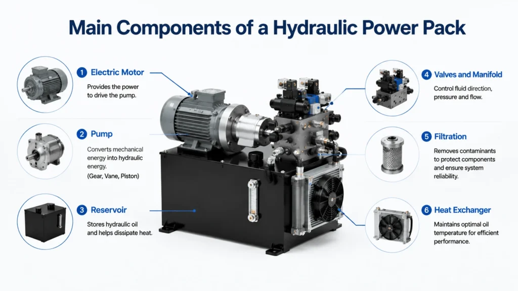
Main Components of a Hydraulic Power Pack

Electric Motor

Industrial power packs almost always use a three-phase AC induction motor. Sizes run from 1.5 kW up to 100 kW or more. The motor turns at 1,500 or 1,800 rpm on a 50 or 60 Hz supply, which sets the pump speed and therefore flow.
 
Motor sizing follows the hydraulic power demand plus a margin. If your circuit needs 12 kW of hydraulic power and the pump runs at 90 percent efficiency, the motor must deliver about 13.3 kW. Add 10 to 15 percent for overload margin, and you pick a 15 kW motor. Undersizing causes nuisance trips. Oversizing wastes money and increases the current.

Pump (Gear, Vane, Piston)

The pump sets the flow and pressure capability. Three types dominate industrial power packs: external gear, vane, and piston. Each suits a different pressure band, noise target, and budget.
Gear pumps run 0.5 to 100 cc/rev and top out near 250 bar. They cost the least and tolerate contamination well.
 
Vane pumps run quieter, suit pressures to 210 bar, and offer fixed or variable displacement. Piston pumps handle 350 to 450 bar, offer variable displacement, and carry the highest efficiency at full pressure. 
 
They also cost the most and demand cleaner oil.The selection section below breaks down the trade-off in detail.

Reservoir

The reservoir holds the oil volume the system needs and gives it room to shed air, water, and heat. A tank that is too small causes cavitation, foaming, and overheating. One that is too large wastes floor space and money.
 
Steel tanks dominate industrial units. They take threaded ports, resist permeation, and ground the system. Stainless steel suits food, pharma, and marine service where rust cannot be tolerated. The tank needs a vented breather, a suction strainer, a return line diffuser, and a drain port at the lowest point.

Valves and Manifold

The manifold bolts the control valves into one block. A relief valve sets a maximum pressure. A directional valve, usually a 4/3 solenoid spool, routes flow. A check valve holds the load. A pressure-reducing valve feeds a secondary circuit at a lower pressure.
 
Manifold construction cuts leak points and pipe runs compared with piped valving. It costs more up front but pays back in fewer leaks and faster service. CETOP and ISO 4401 mounting patterns (NG6, NG10, NG16, NG25) let you swap valves without changing the block.

Filtration

Filtration decides component life more than any other factor. A typical power pack carries a return line filter that cleans oil before it re-enters the reservoir. A suction strainer protects the pump inlet. High-pressure circuits add a pressure filter downstream of the pump.
 
Return line filters target ISO 4406 20/18/15 for general service. Proportional and servo valves demand 18/16/13 or cleaner. An offline kidney loop filter, running independently of the main circuit, holds cleanliness steady during idle periods. We cover targets and locations in the filtration section.

Heat Exchanger

Oil temperature should stay between 45 and 55 °C in service. Above 65 °C, viscosity drops, internal leakage rises, and seal life falls fast. A heat exchanger removes the heat the reservoir cannot shed on its own.
 
Air-blast coolers use a fan and a finned core. They suit most indoor industrial packs where water is scarce or dirty. Water-cooled shell-and-tube or plate exchangers handle high heat loads where clean cooling water exists. Both need a thermostat to run only when the oil exceeds the setpoint, which saves energy and avoids overcooling.

Key Specifications

 
Spec Typical range Notes
Motor power
1.5–100 kW
3-phase AC induction, 1500/1800 rpm
Pump type
gear / vane / piston
fixed or variable displacement
Pump displacement
0.5–250 cc/rev
sets flow at motor speed
Max pressure
70–450 bar
relief or pump limit
Flow at pressure
5–400 L/min
falls as pressure rises on fixed pumps
Reservoir volume
10–1000 L
2–3× pump flow per minute
Duty cycle
S1 continuous or S2 intermittent
S1 for production lines
Oil grade
ISO VG 32 / 46 / 68
VG 46 most common
Cleanliness target
ISO 4406 20/18/15 to 18/16/13
tighter for servo/proportional
Port standard
SAE J1926 / ISO 6149 / BSPP / CETOP
varies by region
Noise
60–75 dB(A)
enclosure cuts 5–10 dB
Flow drops as pressure climbs on fixed-displacement pumps, because internal leakage grows with pressure. Always read flow at the pressure your circuit actually needs, not at zero pressure.

Pump Selection: Gear vs Vane vs Piston

Feature External gear Vane Piston
Pressure range
up to 250 bar
up to 210 bar (fixed), 320 bar (variable)
350–450 bar
Displacement
fixed
fixed or variable
fixed or variable
Efficiency at full pressure
85–90%
90–92%
92–95%
Noise
moderate
low
moderate to high
Contamination tolerance
high
medium
low
Cost
lowest
medium
highest
Best use
low-cost fixed flow, mobile
quiet industrial, mid-pressure
high-pressure, variable, servo
Pick a gear pump when cost matters more than efficiency and pressure stays under 250 bar. Material handling, simple presses, and clamping circuits fit here. The pump runs cheap and shrugs off dirt that would kill a piston unit.
 
Pick a vane pump when noise matters, and pressure stays moderate. Machine tools and indoor industrial lines favor vane pumps because they run quieter than gear units. Variable vane pumps also save energy by trimming flow at idle.
 
Pick a piston pump when pressure exceeds 320 bar, or you need variable displacement with closed-loop control. Presses, injection molders, and servo systems use axial piston pumps for their efficiency and response. Pay the price in higher cost and tighter cleanliness requirements.

Fixed vs Variable Displacement

A fixed-displacement pump moves the same volume every revolution. Excess flow dumps across the relief valve at full pressure when the circuit does not need it. That dumped flow turns straight into heat. Fixed pumps suit simple circuits with constant demand and low duty.
 
A variable-displacement pump adjusts stroke to match demand. When the circuit needs less flow, the pump strokes and draws less motor power. Pressure stays near the compensator setting without dumping flow across a relief. Variable pumps cut heat and energy use in circuits with varying demand.
 
The rule: if your circuit idles often or varies flow widely, a variable pump pays back in energy and cooling savings. If it runs full flow at full pressure most of the time, a fixed pump is simpler and cheaper.

Sizing a Hydraulic Power Pack

Three numbers drive selection: force, speed, and runtime.
Force sets pressure. Say you need 200 kN from a 100 mm bore cylinder. Area is 0.00785 m². Pressure equals force over area, so 200,000 N / 0.00785 m² = 25,500 kPa, or about 255 bar. That points to a piston pump, not a gear pump.
 
Speed sets flow. To extend that 100 mm bore cylinder at 100 mm/s, you need a flow equal to area times speed. That gives 0.00785 m² × 0.1 m/s × 60 = 47 L/min. Pick a pump that delivers 47 L/min at 255 bar, plus margin.
 
Runtime sets motor power. Hydraulic power equals pressure times flow, divided by 600 for bar and L/min. Here, 255 × 47 / 600 = 20 kW. At 92 percent pump efficiency, the motor must deliver about 21.7 kW. Add a 15 percent margin and you pick a 22 or 30 kW motor.

Reservoir Sizing

Reservoir volume should equal 2 to 3 times the pump’s flow per minute. A pump delivering 50 L/min wants a 100 to 150 L tank. This rule gives oil enough dwell time in the tank to release air and let contaminants settle.
 
Dwell time matters because oil returning from the cylinders carries air bubbles and heat. A tank that is too small sends that oil straight back to the pump, which causes cavitation and foaming. A larger tank gives the oil time to settle and cool.
 
In mobile or space-constrained packs, you can run smaller, down to 1 times pump flow, but you must add better cooling and filtration to compensate. Stationary industrial packs should hold to the 2 to 3 times rule. Add 10 percent for thermal expansion and low-level alarms.

Cooling and Heat Rejection

A power pack rejects roughly 15 to 25 percent of input power as heat. The exact figure depends on pump efficiency, valve losses, and how often the circuit dumps flow across a relief. A 22 kW unit running hard generates about 3 to 5 kW of heat that the cooler must remove.
 
Calculate cooler size from that heat load plus the reservoir’s own heat dissipation. A bare steel tank sheds about 0.5 kW per 100 L of surface area at a 40 °C rise. If the tank handles 1 kW and the system generates 4 kW, the cooler must remove 3 kW.
 
Pick an air cooler for indoor service where water is unavailable. Pick a water cooler when clean process water exists, and heat loads run high. Size the cooler for the worst-case duty, not the average, or the pack overheats on the days it works hardest.

Filtration Strategy

Filter location Target Protects
Suction strainer
coarse, 100–150 μm
pump inlet
Return line
10 μm, ISO 20/18/15
reservoir and pump
Pressure line
5–10 μm, ISO 18/16/13
downstream valves
Offline kidney loop
3–5 μm, ISO 17/15/12
whole system during idle
Suction strainers protect the pump from large debris. Return line filters catch most contamination before it re-enters the tank. Pressure filters protect proportional and servo valves that cannot tolerate dirt.
 
The kidney loop is the component most buyers skip. It circulates oil through a fine filter at low pressure, independent of the main circuit. Running it during idle periods and overnight holds cleanliness tight even when the machine sits. For proportional and servo systems, a kidney loop is not optional.

Duty Cycle: S1 vs S2

Duty cycle sets how long the motor can run without overheating. S1 means continuous duty. The motor runs at rated load indefinitely, and its temperature stabilizes below the insulation limit. Production lines, presses, and process machinery need S1.
 
S2 means short-term duty. The motor runs at rated load for a fixed period, then rests to cool. A label might read “S2-30 min,” meaning 30 minutes on followed by a long cool-down. S2 suits intermittent service like lifts, clamps, and positioning moves.
 
Matching the duty cycle to the application is the spec most often ignored. An S2 motor in an S1 application overheats and trips within hours. An S1 motor in an S2 application costs more and runs oversized, but it survives. When in doubt, buy S1.

Noise and Enclosure

Industrial power packs run between 60 and 75 dB(A) at one meter. Gear pumps and piston pumps sit at the louder end. Vane pumps and slower speeds run quieter. Motor fans and relief valve chatter add to the total.
 
An acoustic enclosure cuts noise by 5 to 10 dB. The enclosure must still allow cooling air in and out, or the pack overheats. Louvers lined with sound-absorbing foam and a separate ventilation fan handle both jobs. Specify the enclosure to the actual dB target, not a generic “low noise” request.
 
In machine tools and indoor lines, noise limits often drive pump selection. A vane pump at 65 dB may cost more than a gear pump at 72 dB, but it lets you skip the enclosure entirely.

Common Applications

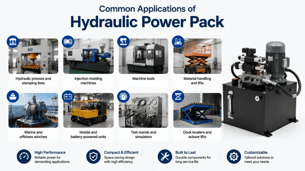
Common Applications of Hydraulic Power Pack
  • Hydraulic presses and stamping lines: high pressure, variable piston pumps, S1 duty
  • Injection molding machines: variable displacement, servo-proportional control
  • Machine tools: clamping and feeding, vane pumps for low noise
  • Material handling and lifts: intermittent S2, gear pumps, manual release
  • Marine and offshore winches: stainless hardware, biodegradable oil
  • Mobile and battery-powered units: 12V and 24V DC packs (see our DC power unit guide)
  • Test stands and simulators: variable pumps, accumulator circuits, closed-loop control
  • Dock levelers and scissor lifts: compact packs, single-acting cylinders

Common Failures

Overheating ranks first. Causes include an undersized cooler, a relief valve stuck open, a clogged filter, or running an S2 motor on S1 duty. Check oil temperature first. If it climbs past 65 °C, shut down and find the heat source before seals fail.

Pump failure usually traces to contamination. Dirt scores the gear teeth or piston bores, internal leakage rises, and flow falls. A pump that ran fine for years then loses pressure in a week almost always ingests dirt through a failed breather or a torn filter seal.

Slow cycle time often comes from a worn pump or a relief valve cracking low, not from low motor power. Gauge pump flow at pressure. If the flow at full pressure drops more than 15 percent from the nameplate, the pump needs a rebuild or replacement.

Motor trips point to overload. Causes include a failing pump bearing, high relief pressure, low voltage, or a stuck valve forcing the pump to deadhead. Check motor current against the nameplate before you swap parts.

Troubleshooting Guide

Symptom Likely cause First check
Oil overheats
undersized cooler, relief stuck open, S2 on S1 duty
oil temperature and cooler operation
Pump noisy / cavitation
clogged suction strainer, cold oil, low level
suction strainer and oil level
Flow drops at pressure
worn pump, contaminated oil, relief cracking low
pump flow test at pressure
Motor trips
overload, low voltage, deadhead, bearing failure
motor current vs nameplate
Won’t hold load
check valve leak, cylinder seal bypass, relief drift
lower loaded cylinder, watch drift
Foamy oil
air ingress, low level, wrong oil grade
suction line fittings and breather

Selection Checklist

  1. Required actuator force sets pressure.
  2. Required speed sets the flow at that pressure.
  3. Pressure and flow band set pump type.
  4. Demand profile sets fixed or variable displacement.
  5. Runtime and idle pattern set S1 or S2 duty.
  6. Flow and dwell time set the reservoir volume.
  7. Heat load sets the cooler type and size.
  8. Valve sensitivity sets the filtration grade and locations.
  9. Noise target sets the pump type and enclosure needed.
  10. The environment sets tank material, oil grade, and port standard.

Maintenance Best Practices

  • Check oil level and temperature daily; top up with the correct ISO VG grade.
  • Sample oil quarterly for ISO 4406 cleanliness and water content.
  • Replace return line filters on differential pressure, not just calendar time.
  • Run the kidney loop during idle periods to maintain cleanliness tight.
  • Inspect motor current annually against the nameplate to catch bearing wear early.
  • Verify relief pressure with a gauge during scheduled service.
  • Change breather elements when they look dirty; a failed breather ingests dirt.
  • Log oil temperature trends to spot cooler fouling before it causes a trip.

FAQ

What is a hydraulic power pack?

A hydraulic power pack is a self-contained unit that generates and controls pressurized oil for a hydraulic circuit. It combines an electric motor, pump, reservoir, control valves, filtration, and often a cooler in one housing. You connect the power and the work ports, and the machine has hydraulic power on demand.

How does a hydraulic power pack work?

An electric motor drives a pump that draws oil from the reservoir through a suction strainer. The pump pushes oil to a manifold, where a relief valve limits pressure and a directional valve routes flow to the cylinders or motors. Return oil passes through a return filter back to the tank, and a heat exchanger removes excess heat.

How do I size a hydraulic power pack?

Match three things: pressure to actuator force, flow to required actuator speed, and reservoir to pump flow. Calculate hydraulic power as pressure times flow divided by 600 (for bar and L/min), then divide by pump efficiency and add a 10 to 15 percent margin to get motor power. Pick a reservoir volume at 2 to 3 times the pump flow per minute.

What oil goes in a hydraulic power pack?

Use a clean anti-wear hydraulic oil. ISO VG 46 suits most industrial services at normal ambient temperature. Use VG 32 for cold climates to avoid startup cavitation, and VG 68 for high-temperature service. Hold cleanliness at ISO 4406 20/18/15 for general service, or 18/16/13 for proportional and servo valves.

Why does my hydraulic power pack overheat?

Overheating usually comes from an undersized cooler, a relief valve stuck open and dumping flow at pressure, a clogged filter, or an S2-rated motor running on S1 duty. Check oil temperature first, then verify that the cooler runs when it should. If the relief pressure reads low, the valve may be bypassing flow and turning it into heat.

How long does a hydraulic power pack last?

A well-specified industrial power pack runs 10 to 15 years with routine maintenance. Pump life typically reaches 15,000 to 20,000 hours with clean oil, and falls to a fraction of that with dirty oil. Motor bearings last 20,000 to 40,000 hours. Oil and filter changes, cleanliness control, and correct duty-cycle matching decide the actual service life.

What is the difference between a hydraulic power pack and a hydraulic pump?

A hydraulic pump is one component that moves oil. A hydraulic power pack is the complete assembly that includes the pump plus the motor, reservoir, valves, filtration, and cooling. The pump generates flow and pressure; the power pack delivers a ready-to-run hydraulic source with all the support systems the pump needs to survive.

Conclusion

A hydraulic power pack trades custom engineering for faster installation and a single point of accountability. Get the spec right, and the unit runs a decade or more. Get it wrong, and you rebuild pumps, swap coolers, and chase overheating every quarter.

The spec that decides service life is not flow and pressure alone. It is pump type matched to the pressure band, reservoir volume matched to dwell time, cooling matched to heat load, and filtration matched to valve sensitivity. Get those four right, and almost everything else follows.

Whether you are specifying a press power pack, replacing a worn machine-tool unit, or diagnosing an overheating clamp circuit, the components, ratings, and sizing math above take you from “which power pack?” to a fully specified, duty-matched unit without guesswork.

Related Articles

Scroll to Top
Shoot Us An Email

Professional Manufacturer