
What is a Hydraulic Distributor?
A hydraulic distributor is a directional control valve assembly that directs hydraulic oil flow to two or more work circuits. Unlike a simple directional valve that controls one actuator, a distributor manages flow distribution across multiple functions simultaneously or sequentially.
The term covers several configurations:
- Sectional valves (stacked monoblock valves)
- Modular valve assemblies (CETOP/ISO mounted)
- Flow divider combiners (priority-based distribution)
- Manifold-mounted directional valves (integrated bank)
Most industrial units operate between 210 and 350 bar (3,000 to 5,000 psi). Mobile equipment versions often reach 420 bar for compact designs. Flow capacities range from 30 L/min to 500 L/min depending on port size and spool geometry.
How a Hydraulic Distributor Works
The basic principle involves a sliding spool inside a machined bore. The spool has lands (wide diameters) and grooves (narrow diameters) that align with internal ports to open or close flow paths.
When the spool shifts:
- One groove connects pressure port (P) to a work port (A or B)
- Another land blocks the alternate work port
- A third groove opens the blocked port to tank (T)
In a multi-section valve assembly, each section controls one actuator. The sections share a common pressure inlet and tank return through an integrated backplate or manifold.
Flow Distribution Methods
| Method | Principle | Best Application |
|---|---|---|
Parallel |
Equal pressure to all circuits |
Low-load simultaneous functions |
Series |
Sequential operation |
High-pressure single-function systems |
Load-sensing |
Flow proportional to demand |
Variable-load mobile equipment |
Priority |
Fixed flow to primary circuit |
Steering/brake priority systems |
Main Components of a Hydraulic Distributor
Spool Assembly
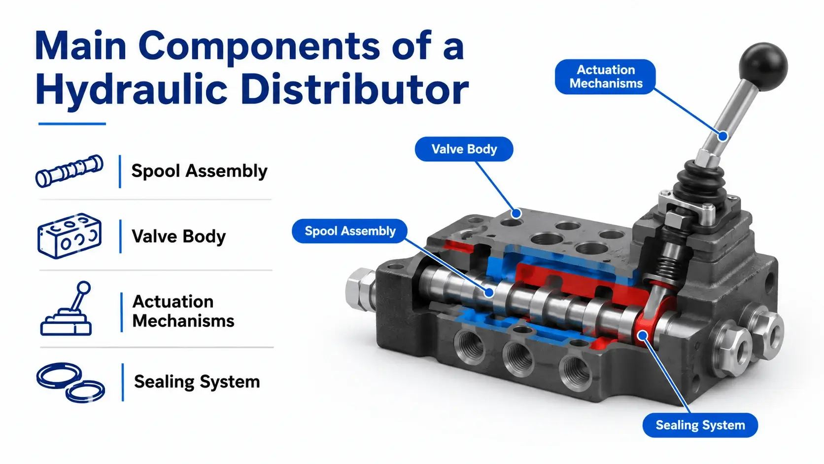
The spool is the moving part that directs flow. Material is typically hardened steel (AISI 5210 or equivalent) with surface hardness HRC 58-62. Critical dimensions include:
- Land diameter tolerance: +0.005/-0.000 mm
- Radial clearance: 5-15 microns (depends on pressure rating)
- Undercut geometry: determines flow characteristic curve (linear, progressive, digressive)
Valve Body
Cast iron or ductile iron handles pressures up to 250 bar. Steel bodies for 350+ bar ratings. The body contains:
- Precision honed bores (Ra < 0.4 μm)
- Internal drilling for P, A, B, T ports
- CETOP mounting pattern (ISO 4401 standard)
- Sectional interface gasket grooves
Actuation Mechanisms
| Type | Force Output | Response Time | Typical Use |
|---|---|---|---|
Solenoid (12V/24V DC) |
20-50 N |
20-50 ms |
Automated sequences |
Pilot hydraulic |
200-800 N |
50-100 ms |
High-pressure systems |
Manual lever |
User-dependent |
Human speed |
Backup/emergency |
Air pilot |
50-200 N |
30-80 ms |
Hazardous areas |
Sealing System
Dynamic seals between spool and body use:
- Cast iron or PTFE composite rings (low friction)
- O-rings at static interfaces (NBR for mineral oil, FKM for high temp)
- Wiper seals on exposed rods (dust exclusion)
Advantages of Using a Hydraulic Distributor
Compact system integration
One hydraulic distributor replaces multiple individual valves, reducing plumbing connections by 60-80%. Fewer fittings mean fewer leak points.
Simplified control logic
All directional functions centralize in one location. Electric solenoid bundles terminate at a single junction box instead of scattered wiring.
Lower installed cost
The valve unit costs more than separate components, but total system cost drops due to reduced hose, fitting, and labor hours.
Easier maintenance access
Troubleshooting concentrates on one physical location. Pressure test points integrate into the manifold for quick diagnostics.
Scalability
Sectional designs allow adding or removing functions without redesigning the entire system. Most manufacturers offer 1-8 section configurations from stock.
Disadvantages and Limitations
Single point of failure
If the valve body cracks or the inlet passage blocks, all downstream functions stop. Redundant systems require a second independent unit.
Higher repair complexity
Disassembling a 6-section valve takes 2-4 hours and requires specialized tools (spool pullers, torque sequence procedures). Individual field-replacement valves swap in 15 minutes.
Pressure drop accumulation
Each section adds 2-5 bar ΔP at rated flow. An 8-section unit might lose 16-40 bar before reaching any actuator. System design must account for this loss.
Cross-port leakage
Spool-to-bore clearance allows internal leakage. At 210 bar, expect 0.1-0.5 L/min per section in neutral. This generates heat and reduces effective flow.
Limited customization
Standard sections offer fixed flow paths. Special center positions or custom porting require long lead-time manufactured sections (8-16 weeks).
Industrial Applications of Hydraulic Distributor
Construction Equipment
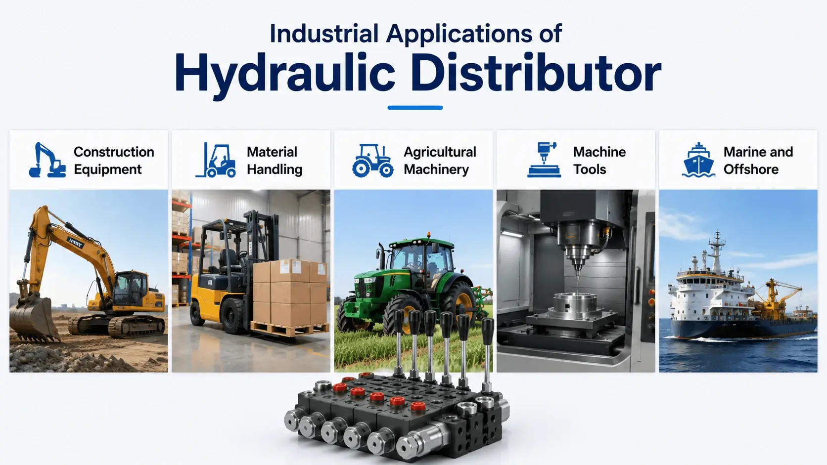
Excavators use a 4-6 section valve bank: boom, stick, bucket, swing, and travel (left/right tracks). Load-sensing versions maintain consistent speed regardless of simultaneous function demands.
Typical specs:
- Pressure: 350 bar continuous, 420 bar peak
- Flow: 120-400 L/min
- Control type: Pilot-operated with proportional solenoid override
Material Handling
Forklifts and telehandlers require 2-4 section units for lift, tilt, sideshift, and attachment functions. Compact monoblock designs fit within the chassis frame.
Agricultural Machinery
Tractors implement 3-point hitches and rear power take-off systems through these valve assemblies with flow combining capability. Rear remote outlets add sections for auxiliary cylinders.
Machine Tools
Press brakes use synchronized valve pairs to balance cylinder forces. CNC machines employ modular CETOP valves for tool clamp, pallet change, and axis clamping.
Marine and Offshore
Winch controls and steering gear use marine-certified distributors (Lloyd’s Register, DNV approval). Materials include bronze or stainless steel for corrosion resistance.
Common Problems and Failure Modes
Spool Sticking
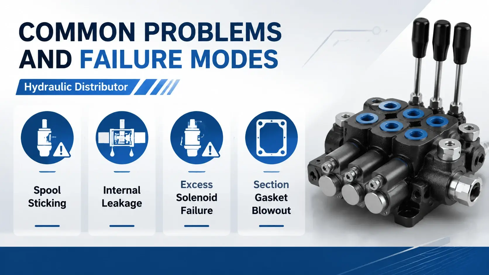
Symptoms: Erratic operation, incomplete shift, solenoid burnout from stalled current.
Causes:
- Contamination particles (>10 microns) lodged in spool lands
- Varnish buildup from oxidized fluid (operating temperature >80°C accelerates this)
- Thermal distortion if cold start at -20°C or below without proper warm-up
Prevention: Maintain ISO 4406 cleanliness code 18/16/13 or better. Change filters per OEM schedule (typically every 2,000 operating hours).
Internal Leakage Excess
Symptoms: Actuator drift under load, overheated oil, pump cycling frequently.
Acceptable leakage rates:
| Pressure | Max Leakage per Section | Test Method |
|---|---|---|
70 bar |
0.05 L/min |
ISO 10767 |
140 bar |
0.15 L/min |
ISO 10767 |
210 bar |
0.35 L/min |
ISO 10767 |
350 bar |
0.80 L/min |
ISO 10767 |
If leakage exceeds these values, check spool bore wear (measure with an internal micrometer) or seal degradation.
Solenoid Failure
DC solenoids fail due to:
- Moisture ingress (burnt coil, shorted windings)
- Over-voltage surge (24V system seeing 30V+ spikes)
- Mechanical binding (spool force exceeds solenoid rating)
Test procedure: Measure coil resistance. Compare to nameplate value ±10%. If resistance reads infinite or near-zero, replace the coil.
Section Gasket Blowout
Between sectional valve interfaces, the gasket seals both pressure and tank passages. Blowout causes external leakage and cross-circuit contamination.
Root causes:
- Uneven bolt torque during assembly
- Reusing compressed gaskets
- Pressure spike exceeding rating (water hammer effect)
Torque specification: Follow manufacturer sequence (typically spiral from center outward). Final torque usually 40-60 Nm for M8 bolts, 80-120 Nm for M10.
Troubleshooting Guide
Diagnostic Flowchart
Problem: No actuator movement
- Check pump output (flow meter at pump outlet)
- Verify pressure at valve P port (minimum 80% of relief setting)
- Test solenoid voltage (should be nameplate ±10%)
- Manually shift spool (use emergency override button)
- If manual shift works but electric does not: solenoid or wiring fault
- If manual shift also fails: mechanical bind or blocked port
Problem: Slow actuator speed
- Measure actual flow at actuator port (should be >90% of pump flow)
- Calculate ΔP across distributor (P port pressure minus A/B port pressure)
- If ΔP > 15 bar at rated flow: worn spool/bore or undersized valve
- Check filter differential pressure (replace if >3 bar)
- Verify fluid viscosity at operating temperature (should be within ISO VG grade range)
Problem: Actuator drift when centered
- Confirm center position (closed-center vs open-center valve)
- For closed-center: measure tank line flow at rest (should be <1 L/min total)
- Isolate each section to locate leaking circuit
- Inspect spool lands for scoring or wear patterns
Selection Guide: How to Specify a Hydraulic Distributor
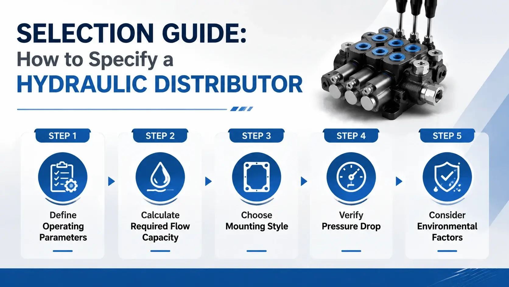
Step 1: Define Operating Parameters
| Parameter | Required Value | Typical Range |
|---|---|---|
Maximum system pressure |
_____ bar |
210 / 280 / 350 / 420 |
Maximum flow rate |
_____ L/min |
30 – 500 |
Number of functions |
_____ sections |
1 – 12 |
Control type |
Solenoid / Pilot / Manual |
– |
Center position |
Open / Closed / Float |
– |
Working fluid |
Mineral oil / HFA / HFD |
– |
Ambient temperature |
_____ °C |
-40 to +60 |
Step 2: Calculate Required Flow Capacity
Step 3: Choose Mounting Style
| Mounting | Advantage | Limitation |
|---|---|---|
CETOP 3 / NG6 |
Compact, standardized |
Limited to 60 L/min |
CETOP 5 / NG10 |
Good mid-range option |
Requires more space |
CETOP 7 / NG16 |
High flow capacity |
Heavy, expensive |
Sectional monoblock |
Customizable sections |
Longer lead time |
Modular subplate |
Flexible configuration |
More potential leak points |
Step 4: Verify Pressure Drop
Request the manufacturer’s pressure-flow curve. Ensure that at your operating flow, the ΔP per section stays below 5 bar (or your system’s allowable budget).
Rough estimate formula: ΔP ≈ (Q / Q_rated)^2 × ΔP_rated
Where Q equals actual flow, Q_rated equals valve’s nominal flow rating, and ΔP_rated equals published drop at nominal flow.
Step 5: Consider Environmental Factors
- Temperature below -20°C requires special seals (low-temp NBR or polyurethane). Above +80°C shortens seal life by 50%.
- If your system cannot maintain ISO 18/16/13, specify silt-tolerant spool clearances (accept higher leakage for longer life).
- Impact applications (rock crushers, pile drivers) need shock-rated valves with hardened spools and heavy-duty springs.
Maintenance Procedures
Daily Checks
- Visual inspection for external leaks at section interfaces and port connections
- Listen for abnormal noise (cavitation sounds like gravel in the valve)
- Confirm actuator response matches operator input (no delay or hesitation)
Monthly Inspection
- Check solenoid connector tightness and wire insulation condition
- Verify manual override buttons move freely and return to position
- Record system pressure at full load (compare to baseline; rising pressure indicates increasing internal resistance)
Annual Service
- Fluid analysis: Send sample for particle count, viscosity, and water content
- Filter replacement: Change return line and pressure line elements regardless of appearance
- Torque check: Retighten sectional valve mounting bolts to specified torque
- Function test: Stroke each section through full range while monitoring pressure and flow
Rebuild Interval
Plan major overhaul at 5,000-8,000 operating hours when any of these conditions appear:
- Internal leakage exceeds 2× new-valve spec
- Spool force exceeds 20% of actuator rating
- Visible damage to spool lands or bore surface
Rebuild requires clean room environment (ISO Class 8 or better). Most users send units to authorized service centers rather than attempt field rebuild.
Frequently Asked Questions
What is the difference between this component and a directional control valve?
A directional control valve typically manages one actuator (single spool, 4-way function). A hydraulic distributor contains multiple directional control valves in one assembly, sharing common inlet and outlet passages. Think of it as a valve bank rather than a single valve.
Can I add a section to an existing valve?
Yes, for sectional designs. Order a matching section, gasket kit, and longer tie-rods (if applicable). Ensure the new section matches the existing flow rating and pressure class. Mixing sections from different manufacturers risks misalignment and leakage.
How do I know if my distributor is open-center or closed-center?
Check the spool center position symbol on the nameplate. Open-center shows P connected to T in neutral (pump unloads). Closed-center shows all ports blocked (pressure holds on system). Float-center connects A to B while blocking P and T.
What causes overheating?
Three main sources: internal leakage (worn spool/bore), excessive pressure drop (undersized valve for the flow), or high ambient temperature with inadequate cooling. Measure tank line flow in neutral. If it exceeds 5% of pump flow, internal leakage is likely the cause.
Should I choose solenoid or pilot actuation?
Solenoid works well up to 350 bar and 50 L/min per section. Above that, or where precise proportional control matters, pilot actuation provides smoother shifting force. Many mobile systems use both: pilot for main functions, solenoid for auxiliary circuits.
What is the typical service life?
With proper maintenance (clean fluid, correct temperature, no pressure spikes), expect 10,000-15,000 operating hours before major overhaul. Harsh environments (mining, marine, foundries) may reduce this to 5,000-8,000 hours. Neglected units can fail in under 2,000 hours.
Conclusion
Selecting and maintaining the right hydraulic distributor directly impacts machine uptime and operating cost. Focus on accurate flow and pressure specifications during design, implement a disciplined maintenance schedule, and train operators to recognize early warning signs of problems. When issues arise, systematic diagnosis using pressure and flow measurements pinpoints faults faster than component swapping.
For application-specific guidance or custom configurations, contact our engineering team with your system parameters. We review submissions within 24 business hours and provide sizing calculations at no charge.