
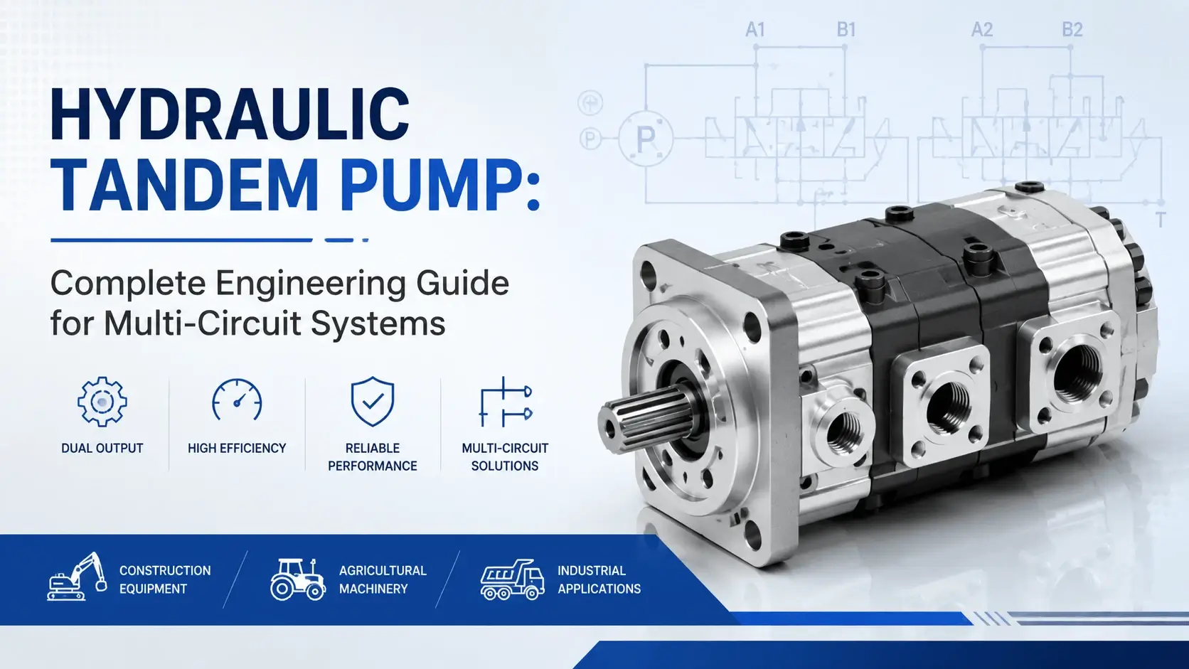
What is a Hydraulic Tandem Pump?
How Tandem Pumps Work
Main Components
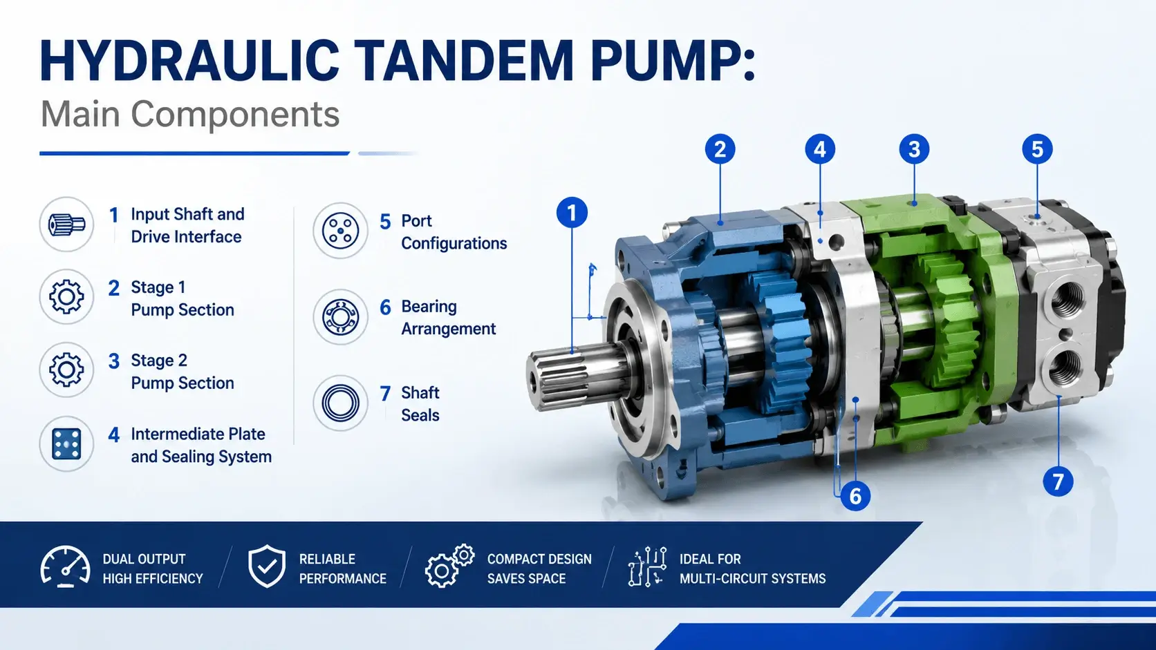
Input Shaft and Drive Interface
Stage 1 Pump Section
Stage 2 Pump Section
Intermediate Plate and Sealing System
Port Configurations
Bearing Arrangement
Shaft Seals
Tandem Pump Configurations
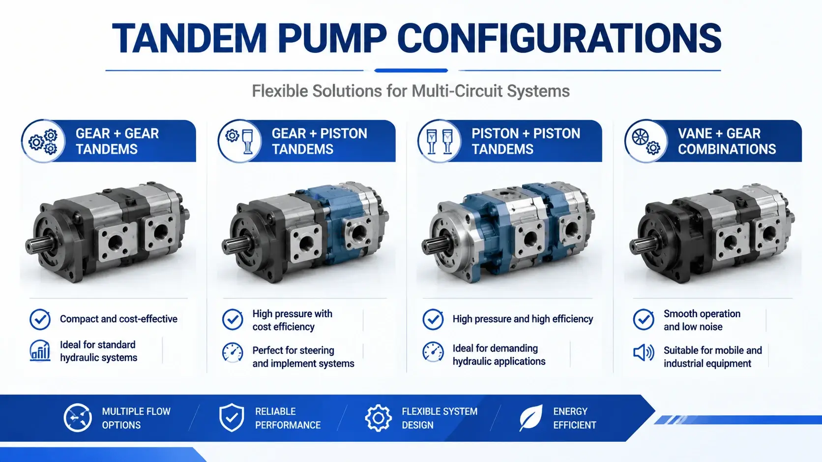
Gear + Gear Tandems
Gear + Piston Tandems
Piston + Piston Tandems
Vane + Gear Combinations
Advantages of Using Tandem Pumps
Space Savings
Installed Cost Reduction
Simplified Alignment
Reduced Plumbing
Single Drive Source
Limitations and Trade-offs
Back-Pressure Effects on Stage 2
Thermal Management Challenges
Single-Point Failure Risk
Maintenance Access Constraints
Sizing Flexibility Limits
Industrial Applications
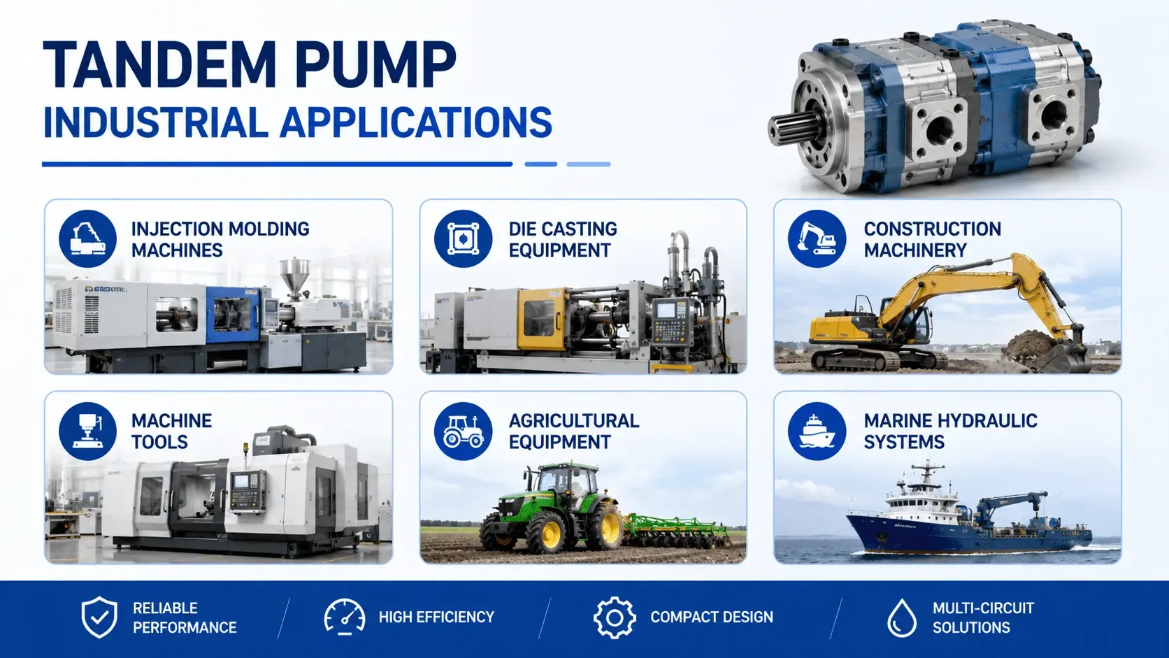
Injection Molding Machines
Die Casting Equipment
Construction Machinery
Machine Tools
Agricultural Equipment
Marine Hydraulic Systems
Selection Guide
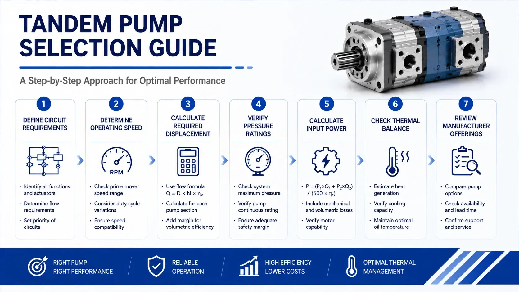
Choosing the right hydraulic tandem pump requires systematic calculation. Follow this procedure.
Step 1: Define Circuit Requirements
List each circuit separately:
Circuit A (main function):
- Maximum flow required: Qa_max = 120 L/min
- Working pressure: Pa = 210 bar
- Duty cycle: 60% of time at full pressure
Circuit B (auxiliary function):
- Maximum flow required: Qb_max = 35 L/min
- Working pressure: Pb = 175 bar
- Duty cycle: 40% of time at full pressure
Step 2: Determine Operating Speed
Your motor or engine dictates pump speed. Electric motors commonly run at 1450 rpm (4-pole, 50 Hz) or 1750 rpm (4-pole, 60 Hz). Diesel engines vary widely. Confirm the actual speed at your expected load, not just nameplate synchronous speed.
Assume 1450 rpm for this example.
Step 3: Calculate Required Displacement
Displacement per revolution equals flow divided by speed (with volumetric efficiency factor):
For Circuit A:Va = Qa_max / (speed × ηv) = 120 / (1450 × 0.92) = 0.090 L/rev = 90 cc/rev
Select standard size: 100 cc/rev (next standard size up)
For Circuit B:Vb = Qb_max / (speed × ηv) = 35 / (1450 × 0.92) = 0.026 L/rev = 26 cc/rev
Select standard size: 25 or 32 cc/rev (25 cc/rev gives slight margin; 32 cc/rev gives more margin but wastes some flow as relief heat)
Choose 25 cc/rev for efficiency.
Step 4: Verify Pressure Ratings
Check that each selected pump section meets or exceeds the required pressure:
- 100 cc/rev gear section: rated 250 bar > 210 bar required. OK.
- 25 cc/rev gear section: rated 250 bar > 175 bar required. OK.
If Circuit B needed 280 bar, you would select a piston section for stage 2 instead of gear.
Step 5: Calculate Input Power
Total hydraulic power determines motor sizing:
Pa_hyd = (Qa × Pa) / 600 = (120 × 210) / 600 = 42 kWPb_hyd = (Qb × Pb) / 600 = (35 × 175) / 600 = 10.2 kWTotal = 52.2 kW
Account for overall efficiency (typically 83-87% for gear-gear tandem at operating point):
P_input = 52.2 / 0.85 = 61.4 kW
Select a 75 kW motor (standard next size up with margin).
Step 6: Check Thermal Balance
Calculate heat generation:
Heat = P_input − P_hyd_useful = 61.4 − 52.2 = 9.2 kW
Reservoir must dissipate this heat. Rule of thumb: reservoir volume should be 3-5 times total flow per minute. Total flow here is 155 L/min. Minimum reservoir: 465 liters. If ambient temperature is high or duty cycle is continuous, add a water-oil or air-oil cooler sized for 10-12 kW rejection.
Step 7: Review Manufacturer Offerings
Now you know what you need: 100 + 25 cc/rev, 250 bar, 1450 rpm, SAE J mounting. Contact manufacturers with these specs. Compare lead time, price, local support availability, and warranty terms. A hydraulic tandem pump from a reputable supplier with service network access reduces long-term ownership risk.
Troubleshooting Common Issues
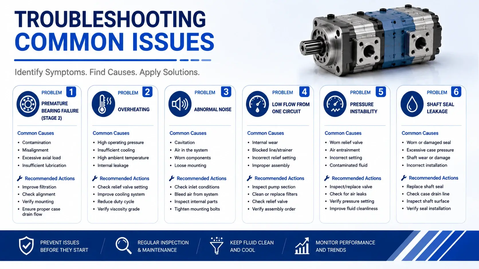
Field problems with tandem pumps follow patterns. Recognizing these patterns speeds diagnosis.
Problem 1: Premature Bearing Failure (Stage 2)
Symptoms: Noise increases gradually over weeks. Metal particles appear in the filter element. Eventually, shaft locks or seizes.
Common cause: Coupling misalignment puts radial load on the input shaft. The cantilever effect amplifies at the distant stage 2 bearing. A misalignment of 0.15 mm TIR at the coupling can produce 0.05 mm deflection at the rear bearing, cutting L10 life by 60-70%.
Fix: Laser-align motor and pump to within 0.05 mm TIR angular and offset. Check coupling condition. Replace worn elastomer elements. Use spacer couplings for longer tandem units to reduce overhang moment.
Problem 2: Overheating
Symptoms: Oil temperature exceeds 60°C within 30 minutes of startup. Pump case feels too hot to touch comfortably.
Causes:
- Reservoir undersized for the total flow (both stages combined)
- Relief valves set too close to working pressure, causing constant overflow
- Internal leakage increased due to wear (check flow at low pressure vs. rated pressure)
- Cooler plugged or fan failure (if equipped)
- Viscosity too low for operating temperature (oil thinning reduces lubrication film)
Diagnostic steps: Measure flow from each stage separately using a flow meter. Compare to catalog values at same speed and pressure. A drop greater than 15% indicates wear. Check relief valve settings with calibrated gauge. Verify cooler operation.
Problem 3: Abnormal Noise
Whining or screaming noise suggests cavitation. Air entrainment causes a rattling or grinding sound.
Cavitation causes:
- Inlet restriction (collapsed hose, clogged strainer, undersized line)
- Oil viscosity too high for cold start
- Inlet pressure below -0.3 bar (vacuum) at pump port
Air entrainment causes:
- Shaft seal leak sucking air in (common on inlet-side seals)
- Return line above oil level causing aeration
- Low reservoir level exposing inlet pipe
Fix each cause directly. Replace restricted lines. Preheat oil in cold climates. Repair leaking seals. Submerge returns below minimum oil level.
Problem 4: Low Flow from One Circuit
When Circuit A works normally, but Circuit B has weak or slow action, the issue isolates to stage 2 or its circuit.
Check sequence:
- Verify stage 2 relief valve setting (may have drifted low)
- Check for external leak in circuit B plumbing
- Measure stage 2 flow with a flow meter
- If flow is low at low pressure, internal wear is likely
- If flow is normal at low pressure but drops at pressure, check intermediate plate sealing
Internal leakage between stages through a failed intermediate seal mimics stage 2 weakness. The oil goes somewhere, just not where you want it.
Problem 5: Pressure Instability
Oscillating pressure in one circuit while the other remains steady usually indicates a problem in that specific stage or its controls.
Possible causes:
- Worn pressure compensator (if variable displacement)
- Trapped air in the circuit (needs bleeding)
- Accumulator precharge incorrect (if fitted)
- Valve spool sticking due to contamination
Isolate the affected circuit systematically. Swap relief valves between circuits if possible to rule out valve issues.
Problem 6: Shaft Seal Leakage
Oil dripping from the shaft end indicates seal failure. Minor weeping (a few drops per hour) warrants monitoring. Steady streaming requires immediate attention.
Causes:
- Normal wear after 8,000-12,000 hours of operation
- Shaft surface scored or corroded
- Excessive case pressure (drain line blocked or restricted)
- Misalignment-induced shaft eccentricity loading the seal lip
Replace seal and inspect shaft condition. Polish light scoring with fine emery cloth. Deep scores require shaft replacement or sleeve installation. Verify case drain line is open and unrestricted.
Maintenance Protocol
Preventive maintenance extends hydraulic tandem pump life significantly. Follow this schedule.
Daily Checks (Operator Level)
- Visual inspection for leaks at all ports and shaft seal
- Listen for abnormal noise (cavitation sounds, bearing whine)
- Check oil level in reservoir
- Note oil color and clarity (milky equals water, dark equals oxidation)
- Observe case temperature (should be warm, not hot enough to sizzle droplet)
Weekly Checks (Technician Level)
- Check and record system pressures at working conditions
- Inspect filter differential indicator; change element if indicated
- Sample oil for analysis (particle count, moisture, viscosity)
- Tighten mounting bolts to specified torque
- Verify cooler operation (airflow or water flow)
Monthly Checks (Engineer Level)
- Laser verify shaft alignment (document readings)
- Test relief valve cracking pressure
- Measure flow from each stage at operating pressure
- Compare to baseline data taken at commissioning
- Inspect coupling element for cracks or hardening
- Check hose condition at all connections
Annual Overhaul (or per 8,000-10,000 hours)
- Remove pump for bench inspection
- Measure internal clearances (gear tooth wear, piston/cylinder clearance)
- Replace all seals (shaft seals, O-rings, gaskets)
- Inspect bearings for play or race damage
- Replace bearings proactively if near calculated L10 life
- Rebuild with new intermediate plate gasket
- Record measurements for trend analysis
Storage Procedures
If removing pump from service for extended period:
- Drain oil completely
- Flush with light oil if contaminated
- Fill with ISO VG 32 corrosion-inhibiting oil
- Rotate shaft by hand monthly to re-distribute oil film
- Seal all ports with caps or plugs
- Store indoors, horizontal position, off the floor
Store in a climate-controlled environment if possible. Temperature swings cause condensation inside the housing, leading to internal rust during long storage periods.