
This guide covers what a hydraulic servo valve is and how the torque motor and pilot stage actually work. It explains how to size one using the 70 bar convention and how to keep it alive once installed.
What is a Hydraulic Servo Valve?
A hydraulic servo valve is an electro-hydraulic valve. It controls flow or pressure with high precision in response to a low-power electrical input. The input drives a torque motor, which moves a pilot stage. The pilot stage produces a pressure differential that positions the main spool. A feedback mechanism closes the loop between spool position and torque-motor deflection so the spool tracks the command.
The defining feature is the spool geometry. Servo valves use a critical-center, zero-lap (or slightly negative-lap) spool. The spool lands line up exactly with the port edges at neutral, so there is no dead band around center. Flow reverses the instant the command reverses. That is what gives a servo valve its precision. It is also what forces the valve to leak at neutral and to demand glass-clean oil.
Place servo valves in the family by accuracy and cost. They sit above proportional valves and well above on/off solenoid valves. A servo valve gives you bandwidth and precision that no proportional valve can match. It costs 3–5× more than a comparable closed-loop proportional valve and needs oil of two cleanliness grades cleaner.
How a Servo Valve Works

The torque motor
The torque motor is the electrical-to-mechanical interface, and it behaves nothing like a proportional solenoid. A proportional solenoid produces a force proportional to current across a few millimeters of stroke. A torque motor produces torque proportional to current across a fraction of a degree of rotation. The armature sits between two permanent magnets. A current in the coil pushes the armature one way or the other by a small angle.
That small angle is the entire input to the pilot stage. The armature connects rigidly to the flapper in a flapper-nozzle valve. In a jet-pipe or deflector-jet valve, it connects to the jet deflector. Either way, a few milliamps of command current become a few hundredths of a millimeter of movement at the pilot stage. The torque motor is fast; its mechanical time constant is in the low milliseconds. That is why servo valves respond at tens to hundreds of hertz.
The pilot stage: flapper-nozzle, jet pipe, deflector jet
The pilot stage turns a tiny mechanical deflection into a pressure differential, and it does so by metering fluid. Three architectures dominate the market, and the choice between them is a real engineering decision.
In a flapper-nozzle valve, pressurized oil feeds two fixed nozzles through matched orifices. The flapper sits between the nozzle tips. When the flapper is centered, both nozzles see the same gap and produce the same back-pressure. The two ends of the main spool see equal pressure. When the torque motor deflects the flapper toward one nozzle, that nozzle’s back-pressure rises and the opposite one falls. The pressure differential pushes the spool. The nozzle gaps are tiny, often 0.05–0.1 mm. A single contaminant particle can silence the stage.
In a jet pipe valve, a nozzle on a flexible tube directs a stream of oil at two receivers. When the tube is centered, both receivers catch equal flow, and the pressures balance. When the torque motor deflects the tube, one receiver gets more flow, and its pressure rises. The jet pipe’s metering area is larger than a flapper-nozzle gap, so it tolerates more contamination. The trade-off is a slightly slower response and a more complex construction.
A deflector jet valve works on the same principle. It moves a flat deflector plate between a fixed nozzle and two fixed receivers. The deflector redirects the jet rather than moving the nozzle itself. This keeps the oil passages short and rigid, which pushes the resonant frequency up and improves contamination tolerance further. Most modern “contamination-tolerant” servo valves are deflector-jet designs.
The second stage: critical-center spool and mechanical feedback
The pilot stage produces a pressure differential across the second-stage spool, and the spool moves. The question is how the valve knows when to stop. The answer is mechanical feedback.
A thin wire or spring connects the end of the main spool back to the flapper or jet deflector. Engineers call it the feedback spring or feedback wire. As the spool moves, the feedback spring exerts a torque on the flapper that opposes the torque-motor command.
The spool keeps moving until the feedback torque exactly balances the command torque. At that point, the flapper recenters, and the pressure differential across the spool drops to zero. The spool holds its position.
This is an elegant, self-contained, closed loop with no electronics in the oil. It is also the reason a two-stage servo valve does not need an LVDT on the main spool. The mechanical feedback closes the loop, and the loop is fast because it is entirely hydraulic and mechanical. The penalty is that the feedback spring is a wear and fatigue item. A damaged spring shows up as gain change or limit cycling.
Three-stage valves and electrical feedback
Two-stage servo valves top out at roughly 150–400 L/min of rated flow. The pilot stage can only generate so much force against the main spool. For larger flows, you need a third stage.
A three-stage servo valve uses a complete two-stage servo valve as its pilot. The two-stage pilot positions a large main spool, and an LVDT measures the main spool’s actual position. The LVDT signal goes to a servo controller that drives the pilot valve. The loop is now closed electrically rather than mechanically. The controller does the work that the feedback spring did in the two-stage valve.
Three-stage valves handle thousands of L/min and are common on large test rigs, steel mill AGC systems, and big simulators. They cost more and need a controller, and the electrical loop is slower than a mechanical loop. At those flows, though, there is no alternative.
Servo Valve vs Proportional Valve vs On/Off Valve
The three valve families look similar from the outside, but solve different problems. The differences lie in the actuator, the spool geometry, the cleanliness demand, and the bandwidth.
| Characteristic | On/off directional valve | Proportional valve | Servo valve |
|---|---|---|---|
Control |
Discrete positions (2 or 3) |
Continuous, proportional to signal |
Continuous, high precision |
Actuation |
Switching solenoid |
Proportional solenoid |
Torque motor + pilot stage |
Spool overlap |
Positive overlap (covers flow) |
Slight positive overlap (dead band) |
Zero or slight negative overlap |
Hysteresis |
Not applicable |
1–6% open-loop, <0.3% closed-loop |
0.1–0.5% |
Frequency response (-3 dB) |
<5 Hz |
5–30 Hz (high-response up to ~60 Hz) |
50–150+ Hz |
Position feedback |
None |
Optional (LVDT) |
Mechanical (2-stage) or LVDT (3-stage) |
Rated flow convention |
Nominal pressure |
5 bar per control edge |
70 bar per control edge |
Oil cleanliness (ISO 4406) |
21/19/16 acceptable |
18/16/13 recommended |
15/13/11 or cleaner |
Relative cost |
1× |
3–8× |
10–25× |
The rated-flow row is the one that trips up engineers moving from proportional to servo work. A proportional valve rated at 80 L/min at 5 bar per edge flows roughly 220 L/min at a 40 bar drop. A servo valve rated at 80 L/min at 70 bar per edge runs at a much higher pressure drop. The same 80 L/min number means a physically smaller, faster valve. Size a servo valve using proportional conventions, and you will buy a valve far too large for the loop.
The cleanliness row decides whether the valve survives. A servo valve’s flapper-nozzle gaps run 0.05–0.1 mm. A proportional valve’s spool-to-bore clearance is an order of magnitude larger. The oil regime that keeps a proportional valve happy will wreck a servo valve in days.
Pilot-Stage Architectures Compared
The pilot stage is where most servo valve selection and most servo valve failures actually happen. The three architectures trade off bandwidth, contamination tolerance, and cost.
| Architecture | Contamination tolerance | Frequency response | Complexity | Typical use |
|---|---|---|---|---|
Flapper-nozzle |
Low (smallest gaps) |
Highest (up to 150+ Hz) |
Moderate |
Aerospace, high-bandwidth test rigs, simulators |
Jet pipe |
Moderate |
High (slightly lower) |
Higher |
Industrial, mobile, applications with marginal filtration |
Deflector jet |
Moderate-high |
High |
Higher |
Modern industrial servo, replacements for flapper-nozzle |
I lean toward deflector-jet valves for most industrial work. You give up a small amount of bandwidth, and you gain real-world reliability. Flapper-nozzle still wins when you need every hertz of response — flight control and the highest-bandwidth test rigs. The jet pipe sits in between. It has a loyal following in marine and mobile work, where the oil is never as clean as the valve wants.
Key Specifications and What They Mean
Rated flow at 70 bar per control edge
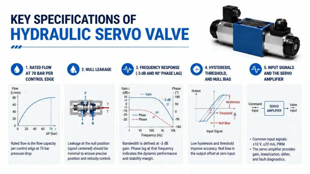
Servo valve manufacturers rate flow at 70 bar (7 MPa, ~1000 psi) total pressure drop across the valve. That works out to 35 bars per control edge for a four-way valve. Some data sheets quote 70 bar per control edge; read the fine print. This convention exists because servo valves operate at high pressure drops. The valve is intentionally a restrictive element in the circuit so it can meter precisely.
A valve rated at 40 L/min at 70 bar flows more at a higher pressure drop, following the square-root law. The law is Q = Q_rated × √(Δp_actual / Δp_rated). At a 210 bar drop across the valve, that same 40 L/min valve flows about 69 L/min. Size of the rated flow at the rated drop. Then check that the actual operating drop gives the flow the actuator needs.
Null leakage
A zero-lap spool cannot seal at neutral. The lands do not overlap the ports. A small flow always passes from supply to return through the metering edges. Add the continuous flow through the pilot stage. A flapper-nozzle valve bleeds supply to both nozzles and to the tank all the time. So a servo valve leaks even with the spool centered and the actuator stationary.
Null leakage is typically 2–5% of rated flow for the second stage, plus 0.5–2 L/min of pilot flow. On a 40 L/min valve, that might be 1–2 L/min of continuous bleed. It sounds small, but it runs 24/7, it heats the oil, and it consumes pump capacity. If you size a power unit by actuator flow alone, the servo valve leakage will eat your margin.
Frequency response (-3 dB and 90° phase lag)
Frequency response tells you how fast the valve tracks a sinusoidal command. It is the number that decides whether your loop will close. Two figures matter. The -3 dB amplitude ratio frequency is where the output amplitude has fallen to 70.7% of the input. The 90° phase-lag frequency is where the output lags the input by a quarter cycle.
A typical two-stage flapper-nozzle servo valve quotes a -3 dB frequency of 100–150 Hz. Its 90° phase lag runs around 40–80 Hz, depending on size and pressure. A proportional valve of the same flow quotes 10–30 Hz. That tenfold difference is why servo valves close high-bandwidth loops and proportional valves do not. When you size a loop, pick a valve whose 90° phase-lag frequency is at least 3–5× your desired closed-loop bandwidth. Otherwise, the valve dynamics will dominate the loop, and you will never tune it stable.
Hysteresis, threshold, and null bias
Servo valve hysteresis runs 0.1–0.5%, driven mainly by the magnetic hysteresis of the torque motor. That is an order of magnitude better than an open-loop proportional valve. Threshold — the smallest input change that produces a spool response — is typically under 0.5% of the rated signal.
Null bias is the input current needed to bring the spool to true neutral. It applies when the feedback spring and torque motor are slightly mismatched. Manufacturers specify it (often under 2–3% of rated current), and it drifts with temperature and wear. In a closed loop, the controller trims it out. In an open-loop application, null bias drift shows up as creeping actuator motion at zero command.
Input signals and the servo amplifier
The torque motor draws very little current, typically 10–50 mA for a full-stroke command. It needs a servo amplifier (servo controller) to drive it. The amplifier takes a command signal (±10 V, 4–20 mA, or a fieldbus word). For a three-stage valve, it closes the inner spool-position loop. It also supplies the dither signal that keeps the torque motor and spool moving against static friction.
Dither is a small high-frequency ripple (often 100–400 Hz) added to the drive current. It differs from the dither on a proportional valve. Here, it excites the torque motor, not the spool. It breaks magnetic hysteresis rather than spool stiction. The controller also handles gain, offset, and ramp limiting. On three-stage valves, it closes the main-spool position loop using the LVDT.
Sizing a Servo Valve
Sizing a servo valve is sizing a restrictive metering element, not a full-bore passage. The valve deliberately drops pressure so it can meter, and that pressure drop is part of the cost of precision.
Start with the actuator. Calculate the flow the actuator needs at peak speed: Q_act = A × v. Here A is the annular or full-bore area and v is the peak velocity. Then pick the pressure drop you will allocate to the valve. A common rule is 1/3 of system pressure. For high-dynamic loops, you may allocate more; 1/2 of system pressure is not unusual on test rigs.
Now convert the actuator flow to rated flow at the 70 bar convention. The actual flow through the valve at the operating drop is Q_act. The rated flow is Q_rated = Q_act × √(70 / Δp_valve). If the actuator needs 30 L/min and you allocate a 35 bar drop per edge (70 bar total), the valve is rated at 30 L/min at 70 bar.
If you allocate a 20-bar total drop, you need a 56 L/min valve. Size too large, and the valve operates near null, where null leakage dominates, and resolution is poor. Size too small, and the valve saturates before the actuator reaches peak speed. Aim for the valve to operate between 20% and 80% of rated flow during normal work, with headroom for transients.
Oil Cleanliness Requirements
This is the section that decides whether your servo valve lives for ten years or ten weeks. Servo valves need ISO 4406 cleanliness of 15/13/11 or better. That is two grades cleaner than a proportional valve and four grades cleaner than a typical on/off directional valve circuit.
A 15/13/11 oil sample contains fewer than 320 particles larger than 4 μm(c) per milliliter. To hold that, you need high-efficiency pressure filtration (β₃ ≥ 200, often β₃ ≥ 1000). You also need a kidney-loop filter running continuously and a reservoir designed to settle and shed contamination. Suction strainers alone will not get you there. A single dirty batch of new oil will not either. New oil from the drum is often 22/20/17 and needs filtering before it ever touches a servo valve.
The flapper-nozzle gaps run 0.05–0.1 mm. A silt particle of 5–10 μm looks harmless until it lodges in a nozzle orifice and shifts the null. Silting shows up as null bias drift, threshold increase, and eventually limit cycling. Hard particles larger than the gap score the spool and gall the bore. Both failure modes trace back to oil that was “clean enough” for every other valve on the machine.
Mounting and Porting Standards
Servo valves mount to a manifold using standardized interface patterns. The dominant standard for industrial servo valves is ISO 4401 (CETOP). Common sizes are NG6 (ISO 4401-03), NG10 (ISO 4401-05), and NG16 (ISO 4401-07). Aerospace and mobile servo valves often use proprietary or line-body mountings with SAE J1926 or ISO 6149 threaded ports.
The manifold interface matters more for servo valves than for other valve types. The pilot stage reacts to tiny pressure differences. A poorly machined mounting face, a distorted sub-plate, or an overtightened cap screw can distort the valve body. That shifts the spool bore and changes the null. Torque the mounting bolts to the manufacturer’s spec, in the specified sequence. Check the mounting face flatness when you service the valve.
Common Servo Valve Failures
Contamination silting
The most common failure. Silt lodges in the nozzle orifice or the jet-pipe receiver and shifts the null. The actuator creeps at zero command, or the loop hunts. Flushing sometimes recovers a lightly silted valve. A badly silted valve has to come out and go to a clean bench.
Hard-particle damage
A particle large enough to score the spool or gall the bore. The spool sticks, or the leakage rises until the actuator will not hold. This is usually fatal. The valve needs a rebuild or replacement, and the oil needs to be fixed before the new valve goes in.
Feedback spring fatigue or damage
The feedback wire that closes the mechanical loop fatigues over millions of cycles. It also gets bent by shock loads or contamination-induced spool jams. Symptoms are gain change (the loop gets sluggish or oscillatory) and limit cycling. The valve needs a factory rebuild to replace and recalibrate the spring.
Torque motor or amplifier fault
The coil burns out (overcurrent, lightning, wiring fault), or the amplifier loses gain. The valve stops responding, or it drives hard to one end. Diagnose with a command sweep at the amplifier and a current measurement at the coil.
Null shift from temperature or pressure
Servo valves drift off null as oil viscosity changes with temperature and as supply pressure varies. A well-tuned closed loop trims this out. An open-loop application shows it as creep.
Troubleshooting Guide
| Symptom | Likely cause | Action |
|---|---|---|
Actuator creeps at zero command |
Null bias drift, silting in pilot stage |
Check null bias at amplifier; flush valve; if persistent, remove and bench-test |
Loop oscillates (limit cycle) |
Feedback spring wear, excessive gain, silting |
Reduce gain and re-test; check oil cleanliness; bench-test valve for gain and null |
Sluggish response, will not track command |
Clogged nozzle, low supply pressure, amplifier fault |
Measure supply pressure; check amplifier output current; inspect pilot stage |
Valve drives hard to one end |
Torque motor coil fault, broken feedback spring, amplifier offset |
Measure coil resistance and current; bench-test valve; replace amplifier or rebuild valve |
Rising null leakage, actuator will not hold |
Spool scoring, worn bore, hard-particle damage |
Bench-test for leakage; rebuild or replace; fix oil before reinstalling |
Intermittent chatter |
Particles passing through pilot stage, marginal filtration |
Sample oil; upgrade filtration; flush system |
Drift with temperature |
Normal null shift not trimmed by loop |
Verify closed-loop controller is active; add temp compensation if open loop |
How to Select the Right Servo Valve
Selection comes down to four decisions, in this order.
First, decide whether you need a servo valve at all. If your loop bandwidth is under 20–30 Hz and a small error is tolerable, a closed-loop proportional valve will usually do the job. It costs a third as much and tolerates two cleanliness grades dirtier oil. Reach for a servo valve when bandwidth, precision, or both push past what proportional can deliver.
Second, pick the pilot stage. Flapper-nozzle for maximum bandwidth and the cleanest oil. Deflector jet for industrial reliability with a small bandwidth penalty. Jet pipe for mobile and marine applications where filtration is marginal.
Third, size the valve on the 70 bar convention using the actuator flow and your allocated pressure drop. Check that the valve operates in its 20–80% flow band during normal work.
Fourth, pick the feedback and electronics. Two-stage with mechanical feedback for flows up to a few hundred L/min. Three-stage with LVDT and servo controller for larger flows. Specify the amplifier, the command signal, and the fail-safe mode (fail-freeze, fail-open, or fail-closed) that matches your safety logic.
Maintenance Best Practices
Keep the oil clean, and the servo valve mostly maintains itself. Monitor ISO 4406 codes monthly, change pressure filters on differential pressure, and never add unfiltered oil to a servo system. Sample at the valve return, not just at the reservoir, because that is where the dirt shows up first.
Check null bias and gain quarterly with a calibrated command sweep. Drift in either number signals silting or feedback-spring wear before the loop starts misbehaving. Keep a spare servo valve on the shelf for critical loops. Send the removed valve to a clean-room rebuild facility rather than opening it on the bench.
Resist the urge to adjust the null screw in the field. The null is set on a flow bench under controlled pressure and temperature. A quarter-turn on the bench in a hot plant will put the valve somewhere no one can predict. If the loop needs a null trim, trim it in the controller.
Industrial Applications
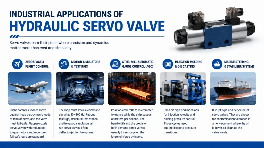
Servo valves earn their place where precision and dynamics matter more than cost and simplicity. The same physics shows up across very different industries.
Aerospace and flight control is the original servo valve application. Flight control surfaces move against huge aerodynamic loads at tens of hertz, and the valve must fail-safe. Flapper-nozzle servo valves with redundant torque motors and monitored fail-safe logic are standard.
Motion simulators and test rigs use servo valves because the loop has to track a command signal at 50–100 Hz. Fatigue test rigs, structural test stands, and hexapod simulators all run servo valves, often deflector-jet for the uptime.
Steel mill automatic gauge control (AGC) positions mill rolls to micrometer tolerance while the strip passes at meters per second. The bandwidth and the precision both demand servo valves, usually three-stage on the large roll-force cylinders.
Injection molding and die casting use servo valves on high-end machines for injection velocity and holding pressure control. Those cycles need sub-millisecond pressure transitions. Marine steering and stabilizer systems run jet-pipe and deflector-jet servo valves. They are chosen for contamination tolerance in an environment where the oil is never as clean as the valve wants.
FAQ
What is a hydraulic servo valve used for?
A hydraulic servo valve is used for high-precision, high-dynamic control of flow, pressure, or position in closed loops that need bandwidth above roughly 30 Hz or accuracy better than 1%. Typical uses include flight control surfaces, motion simulators, fatigue test rigs, steel mill AGC, and high-end injection molding.
How does a flapper-nozzle servo valve work?
A torque motor deflects a flapper between two nozzles. Supply oil feeds both nozzles through matched orifices. When the flapper moves toward one nozzle, that nozzle’s back-pressure rises, and the other falls. The pressure differential pushes the main spool. A feedback spring connects the spool to the flapper and re-centers the flapper when the spool reaches the commanded position.
What is the difference between a servo valve and a proportional valve?
A servo valve uses a torque motor and a pilot stage (flapper-nozzle, jet pipe, or deflector jet) to position a zero-lap spool, giving 50–150 Hz bandwidth and 0.1–0.5% hysteresis. A proportional valve uses a proportional solenoid to position a slight-overlap spool, giving 5–30 Hz bandwidth and 1–6% hysteresis (under 0.3% closed-loop). Servo valves are rated at 70 bar per control edge; proportional valves at 5 bar. Servo valves need ISO 4406 15/13/11 oil; proportional valves tolerate 18/16/13.
Why do servo valves need such clean oil?
The flapper-nozzle pilot stage has metering gaps of 0.05–0.1 mm. Particles that are size or smaller lodge in the nozzle orifice and shift the null, and hard particles score the spool. A 5–10 μm silt particle that every other valve ignores will silence a servo valve. ISO 4406 15/13/11 or cleaner is the practical floor.
What is null leakage in a servo valve?
Null leakage is the continuous flow through a servo valve when the spool is centered, and the actuator is stationary. It comes from two sources: the zero-lap spool cannot seal at neutral, so flow passes the metering edges, and the pilot stage bleeds supply oil to the tank continuously. Total null leakage runs 2–5% of rated flow plus 0.5–2 L/min of pilot flow, and it heats the oil around the clock.
How do I size a servo valve?
Calculate the actuator flow at peak speed, decide the pressure drop you will allocate to the valve (often 1/3 of system pressure), then convert to rated flow at the 70 bar convention using Q_rated = Q_act × √(70 / Δp_valve). Pick a valve whose rated flow lets it operate between 20% and 80% of capacity during normal work.
What causes a servo valve to drift off null? Null drift comes from silting in the pilot stage, temperature-driven viscosity changes, supply pressure variation, feedback spring wear, and magnetic hysteresis in the torque motor. A closed-loop controller trims the drift out; an open-loop application shows it as creeping actuator motion at zero command.
Conclusion
A hydraulic servo valve is the right answer when the loop has to close fast and hold tight, and the wrong answer everywhere else. The precision comes from a torque motor driving a pilot stage that positions a zero-lap spool, with mechanical or electrical feedback closing the loop. That same precision demands 70 bar pressure drops, continuous null leakage, and oil clean enough that most hydraulic systems never achieve it.
If your application needs the bandwidth and the accuracy, a servo valve is unmatched. Size it on the 70 bar convention, keep the oil at ISO 4406 15/13/11, pick the pilot stage that matches your contamination reality, and the valve will do things no proportional valve can. If your application does not need that, a closed-loop proportional valve will save you money, filtration, and grief. Knowing which side of that line you are on is the engineering judgment this guide is meant to support.