
Cleaning Hydraulic Fluid:The Comprehensive Guide

Cleaning Hydraulic Fluid:The Comprehensive Guide

Table of Contents

Why Fluid Cleaning Deserves Serious Attention

Cleaning hydraulic fluid is not glamorous work. It involves hoses, filter carts, and patience. Seventy to eighty percent of hydraulic component failures trace back to contamination. That figure comes from multiple industry studies, including research by Eaton and Parker. Wear debris, water, and chemical breakdown products chew through pumps, score valve spools, and jam actuators. Replacing a single axial piston pump can cost five figures. Replacing all the oil in a 500-liter system costs less than the pump — but only if you catch the problem early.

Yet it delivers one of the highest returns on maintenance spend you will find anywhere in a plant. This guide covers every practical method, tells you which one to use when, and gives you a field procedure you can apply tomorrow.

Clean or Replace? A Simple Decision Framework

Before touching any equipment, answer three questions. First, what is the current ISO 4406 code? Second, what does the lab report say about water content, acid number, and viscosity? Third, what cleanliness level do your most sensitive components require?
If the acid number has exceeded the oil supplier’s discard limit, or if oxidation products have turned the fluid dark and opaque, cleaning will not save it. Drain it, flush the system, and refill. Cleaning works best when the base oil is still sound and the main problem is particulate or water ingress.
Here is a quick reference:
Condition Clean Replace
Particulate above target ISO code
Yes
Only if extreme
Water content under 0.1% (1000 ppm)
Yes
No
Water content over 0.5% (5000 ppm)
Maybe — test first
Likely yes
Acid number near discard limit
Borderline
Yes
Viscosity changed ±15% from new oil
No
Yes
Heavy varnish / sludge visible
Specialized cleanup
Usually yes

What is Actually in Your Dirty Hydraulic Oil?

Contamination falls into three categories. Knowing which one you have determines your cleanup method. Solid particles come from ingressed dust, wear debris from pumps and cylinders, and internal rust. Metal particles are the most damaging because they are hard and sharp.
 
A single 10-micron particle caught in a servo valve clearance can jam the spool. ISO 4406 codes measure particle counts at ≥4 µm(c), ≥6 µm(c), and ≥14 µm(c) channels using calibrated automatic particle counters.
 
Water enters through reservoir condensation, cooler leaks, and bad shaft seals on immersed pumps. Free water settles at the bottom. Emulsified water stays suspended and turns the oil cloudy. Dissolved water is invisible but still accelerates oxidation. Most hydraulic specifications cap water at 0.1% (1000 ppm).
 
Servo systems often demand 0.05% (500 ppm) or lower. Chemical contaminants include oxidation byproducts, additive depletion residues, and varnish precursors. These form as the oil ages, especially above 60°C. They show up as sticky deposits on valve surfaces and dark staining in sight glasses.

Method 1: Portable Filter Carts — The Workhorse Solution

A portable filter cart (also called a kidney loop or filtration trolley) is the most versatile tool for cleaning hydraulic fluid in place. It pulls dirty oil from the reservoir, forces it through high-efficiency filters, and returns clean oil to the tank.

How Filter Carts Work

Typical units consist of an electric motor, a gear pump, a housing for one or two filter elements, and suction/discharge hoses. Flow rates range from 5 to 40 L/min. Higher flow cleans faster but draws more power and generates more heat in the fluid.
 
The critical specification is the filter element beta ratio (β). A β₅(c) = 1000 filter captures 99.9% of particles at 5 microns and larger. For general industrial systems serving gear pumps and directional valves, a 3-micron absolute (β₃(c) ≥ 1000) element is usually sufficient. For systems with servo or proportional valves, drop to 1 micron absolute.

Selecting the Right Filter Cart

System Type Recommended Filter Rating Target ISO Code
General industrial (gear pumps, cylinders)
3 µm absolute, β₃ ≥ 1000
17/15/12
Systems with proportional valves
3 µm absolute, β₃ ≥ 200
16/14/11
Systems with servo valves
1 µm absolute, β₁ ≥ 1000
15/13/11
High-pressure piston pumps (350+ bar)
3 µm absolute, β₃ ≥ 1000
16/14/12

Operating Procedure

Connect the suction hose near the reservoir bottom but clear of sediment. Position the return hose to promote mixing — aim it across the surface or against the opposite wall. Run the cart continuously until particle counts hit the target. For a moderately contaminated 200-liter system at 12 L/min flow, this typically takes 4 to 8 hours. For severely degraded fluid, plan on multiple tank turnovers.

Monitor the differential pressure indicator. If it trips before the job finishes, swap the element. Never bypass a clogged filter.

Method 2: Vacuum Dehydration — Removing Water at Scale

Filter elements trap solids but let water pass through. When water content exceeds roughly 0.1%, you need a different approach. Vacuum dehydration is the most widely used method for bulk water removal in industrial settings.

How Vacuum Dehydration Works

The oil is heated to around 60–65°C and spread into a thin film inside a vacuum chamber. The reduced pressure (typically 25–35 mbar absolute) lowers the boiling point of water. Water flashes off as vapor, which is then condensed and collected. Dry oil exits the chamber and returns to the reservoir.

Good vacuum dehydrators can reduce water content from 2000 ppm to below 100 ppm in a single pass. They handle both free water and a significant portion of emulsified water. Dissolved water equilibrates downward as the concentration drops.

When to Use It

Vacuum dehydration makes sense when:

  • Water content exceeds 1000 ppm and needs to drop fast
  • You have large reservoir volumes (500+ liters)
  • The system runs continuously and cannot be shut down due to draining
  • You already own or can rent a vacuum dehydrator unit

It does not work well on heavily emulsified oils or fluids where water is chemically bound (certain fire-resistant fluids fall into this category).

Method 3: Centrifugal Separation

Centrifuges spin oil at high speed — typically 3000 to 8000 RPM. Density differences force heavier particles and free water outward against the bowl wall. Clean oil stays near the center and gets drawn off.

Centrifuges excel at removing:

  • Large volumes of free water quickly
  • Dense solid particles, especially metals
  • Sediment that would clog conventional filters

They are less effective at fine particles below 10 microns. Most centrifugal separators used in hydraulic service achieve roughly 7–10 micron separation efficiency. That is good enough for rough cleanup on heavy equipment, but not sufficient for servo-grade systems.

The main advantage is throughput. A properly sized centrifuge can process hundreds of liters per hour without consumable filter elements. Operating cost is low once the unit is installed.

Common applications include marine hydraulic systems, steel mill auxiliaries, and turbine lube oil conditioning, where water ingress is constant.

Method 4: Coalescence Technology for Stubborn Water

Coalescers force tiny water droplets to merge into larger ones that settle out or get filtered away. The process uses two stages. First, a coalescing medium (usually glass fiber or treated polymer) combines small droplets. Then, a hydrophobic separator repels the merged water droplets while letting oil pass.

Coalescence handles emulsified water that centrifuges and vacuum dehydrators struggle with. It also removes free water effectively. Typical outlet water levels range from 50 to 200 ppm, depending on inlet conditions and residence time.

The trade-off is maintenance. Coalescer elements foul if the fluid carries heavy particulate loads. Always install a pre-filter upstream of the coalescer stage. Expect to change elements every 3–6 months in continuous service.

Handling Varnish and Soluble Contaminants

Varnish is the silent killer of precision electrohydraulic systems. It forms when oil oxidation byproducts polymerize into sticky, resin-like deposits. These deposits coat valve spools, plug servo valve orifices, and cause sticking that looks like electrical problems.
Standard particle filters do not remove varnish precursors. The molecules are dissolved or colloidal — too small to be trapped by mechanical filtration.
 
Two approaches exist:
Ion exchange resins use charged beads to pull polar oxidation products out of solution. These units look like filter housings but contain resin beds instead of fiber media. They can reduce the Membrane Patch Colorimetry (MPC) varnish potential value from 30+ down to below 15 in a single pass. Replace or regenerate the resin when exhausted.
Surface-charge modified filters carry a slight electrostatic charge that attracts polar contaminants. They offer partial varnish control at a lower cost than full ion exchange systems but are not as thorough.
 
Monitor varnish potential through MPC testing or ultracentrifuge analysis. If MPC exceeds 20, start planning remediation before valves begin hanging up.

Setting Cleanliness Targets for Your Equipment

Not every system needs laboratory-grade oil. Over-cleaning wastes money. Under-cleaning destroys components. Match your target to your most sensitive hardware.
Component Category Minimum ISO 4406 Code Maximum Water Content
Gear pumps, vane pumps, directional valves
18/16/13
0.1% (1000 ppm)
Axial piston pumps (210–350 bar)
17/15/12
0.05% (500 ppm)
Proportional valves
16/14/11
0.05% (500 ppm)
Servo valves
15/13/11
0.02% (200 ppm)
High-response servo (aerospace, simulators)
14/12/9
0.01% (100 ppm)
These numbers come from component manufacturer guidelines including Bosch Rexroth, Parker, Moog, and Eaton. Your specific application may vary based on duty cycle, pressure spikes, and environmental dust load.

Field Procedure: Step-by-Step Fluid Cleaning
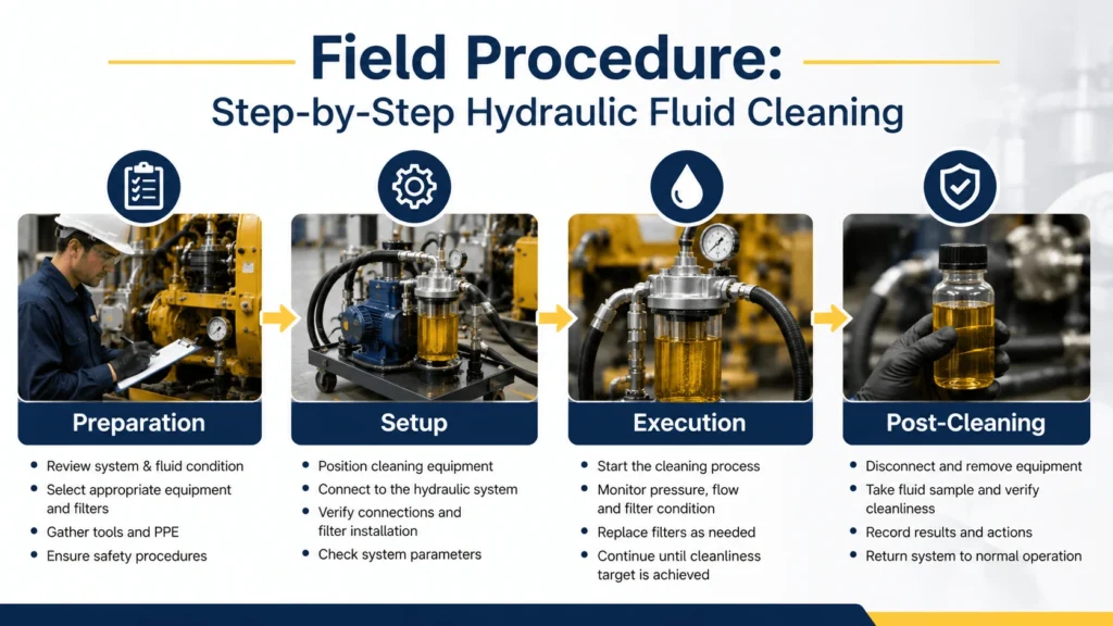
Field Procedure- Step-by-Step Hydraulic Fluid Cleaning

This procedure assumes you are using a portable filter cart on a stationary industrial system. Adjust as needed for other methods.

Preparation

  1. Pull a baseline sample from a live zone port (not the drain valve). Send it to a lab for particle count, water (Karl Fischer), viscosity, and acid number.
  2. Review the results against your target cleanliness level.
  3. Select the appropriate filter element rating based on the table in Section 5.
  4. Inspect the filter cart. Check the element condition, hose integrity, and motor wiring.
  5. Verify the reservoir has adequate working volume. The filter cart needs free oil above the suction point.

Setup

  1. Shut down the main system and lock out power if required by your site protocol.
  2. Connect the suction hose to a dedicated cleaning port or open an inspection port near the tank bottom. Use quick-connect fittings if available.
  3. Route the return hose back to the reservoir. Aim the discharge to create circulation.
  4. Ground the cart if processing flammable fluids or in classified areas.
  5. Power on and confirm the correct rotation direction. Flow should move from the tank, through the filters, back to the tank.

Execution

  1. Run the cart continuously. Log start time and initial differential pressure.
  2. Check differential pressure every 30 minutes. A steady rise indicates the element is loading normally. A sudden spike suggests a problem — shut down and investigate.
  3. After every 3 tank turnovers (reservoir volume divided by cart flow rate), pull a spot sample with a portable particle counter if you have one.
  4. Continue until two consecutive samples meet the target ISO code.
  5. Record final differential pressure, total run time, and end-of-cycle ISO reading.

Post-Cleaning

  1. Send a final lab sample. Confirm results match your portable readings.
  2. Document everything: date, operator, filter type used, start/end ISO codes, hours run, elements consumed.
  3. Return the system to normal operation. Resume regular sampling schedule.

Verifying Your Results

A hand-held laser particle counter gives immediate feedback during cleaning. Units from PALL, Parker, or Hydac report ISO 4406 codes directly. They are accurate enough for trend monitoring but not a substitute for lab analysis.

For certification-quality data, use an ISO 17025-accredited lab. Request:

  • Particle count per ISO 4406:1999 (automatic optical, calibrated)
  • Water content by Karl Fischer titration
  • Kinematic viscosity at 40°C
  • Acid number (ASTM D974 or D664)
  • MPC varnish potential if servo valves are present

Compare pre- and post-cleaning results side by side. A successful cleaning job should show at least two ISO code steps improvement in each channel and water below your target threshold.

Mistakes That Make Things Worse
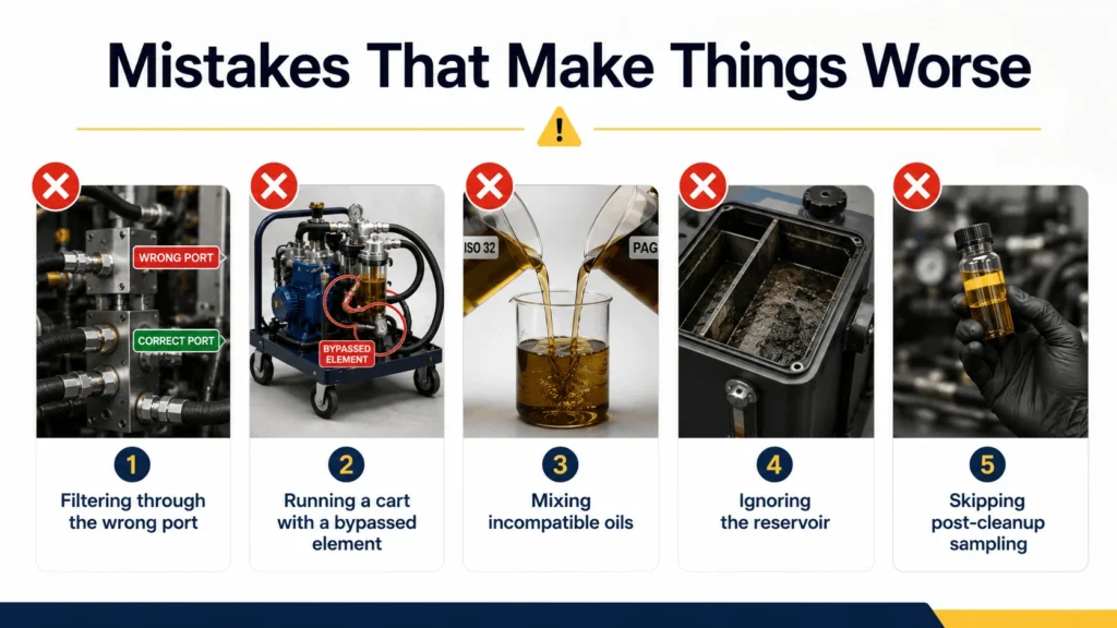
Mistakes That Make Things Worse
Some well-intentioned actions create more contamination than they remove.
Filtering through the wrong port. Drawing oil from the reservoir drain valve pulls the heaviest sediment into your filter cart. If the clogs, that concentrated sludge gets pushed right back into the tank. Use a mid-height sampling port or a dedicated clean-out connection.
 
Running a cart with a bypassed element. When the differential indicator pops, some operators disable the bypass alarm and keep running. Unfiltered oil now circulates through the cart, adding pump-generated wear debris to an already dirty system. Change the element.
 
Mixing incompatible oils. Topping up a system mid-cleaning with a different brand or viscosity grade can destabilize additives and precipitate varnish. Use the same oil specification throughout.
 
Ignoring the reservoir. Cleaning the fluid while leaving sediment, rust scale, and water pooling in the tank bottom guarantees recontamination within days. If the reservoir has never been opened for inspection, this might be the time.
 
Skipping post-cleanup sampling. Assuming the job worked because the cart ran long enough is not verification. One sample costs far less than one premature pump failure.

The Economics: Cleaning vs. Replacement

For a typical 400-liter industrial hydraulic system using ISO VG 46 mineral oil:
Factor Fluid Replacement In-Place Cleaning
New oil (400 L)
1,200 – 1,800
$0
Disposal of waste oil
200 – 400
$0
Labor (drain, flush, refill)
8–12 hours
2–4 hours
Filter elements
0 – 50
80 – 200
Cart rental (if needed)
$0
100 – 300/day
Downtime cost (varies)
Full day minimum
Can run online
Cleaning wins economically in most scenarios where the oil chemistry remains viable. Replacement becomes necessary when oxidation has progressed too far or when the fluid is chemically compromised beyond recovery.
A useful rule of thumb: if the acid number is under 70% of the discard limit and viscosity is within ±10% of nominal, try cleaning first. If either parameter exceeds those bounds, replacement is likely cheaper in the long run.

Conclusion

Cleaning hydraulic fluid is straightforward engineering. The challenge is not technical — it is procedural. Follow the decision framework, pick the right method for your contaminant type, execute the procedure consistently, and verify with lab data. Do those four things and your hydraulic systems will last years longer than they would on a drain-and-fill schedule alone.
The payoff shows up in fewer emergency repairs, lower spare parts consumption, and predictable maintenance windows. That is worth the effort it takes to get the oil right.
 

FAQ

Can you clean the hydraulic fluid instead of replacing it?

Yes, in most cases, the base oil has not chemically broken down. If acid number and viscosity remain within acceptable limits, filtration and dehydration can restore usable fluid to service-ready condition. Lab testing confirms whether cleaning is viable.
 

How do you remove water from hydraulic oil?

Three main methods exist. Vacuum dehydration heats oil under reduced pressure to boil off water vapor — effective down to ~100 ppm. Centrifugal separation spins out free water and dense solids quickly. Coalescence technology merges microscopic water droplets into separable sizes and works well on emulsified water. Choose based on water type, volume, and available equipment.
 

What is the best method for cleaning hydraulic fluid?

Portable mechanical filtration (filter cart) addresses 90% of real-world cases involving particulate contamination. Add vacuum if water exceeds 1000 ppm. Add ion exchange resin treatment if varnish is present in servo systems. No single method handles everything — match the method to the contaminant
 

How clean should hydraulic fluid be?

It depends on your components. Gear pumps and standard directional valves function reliably at ISO 18/16/13. Axial piston pumps prefer 17/15/12 or better. Proportional valves need 16/14/11. Servo valves demand 15/13/11 or cleaner. Consult your component manufacturer’s documentation for exact targets.
 

How often should you filter hydraulic oil?

Continuous offline filtration (kidney loop) running 24/7 at 10% of the main system flow rate maintains cleanliness with minimal intervention. Without continuous filtration, perform batch filtering whenever particle counts exceed the target or quarterly at a minimum — whichever comes first.
 

Can you reuse hydraulic fluid after cleaning?

Yes, provided post-cleaning lab results meet the required ISO code, water content, viscosity, and acid number limits for your application. Document the cleaning cycle and resume routine oil analysis to monitor the degradation rate going forward.
 

How long does it take to clean hydraulic fluid with a filter cart?

A 200-liter system at 12 L/min cart flow typically reaches target cleanliness in 4–8 hours if starting from moderate contamination (ISO 20/18/15 range). Heavily contaminated systems may require 12–24 hours or multiple element changes. Larger systems scale proportionally.

Related Articles

Scroll to Top
Shoot Us An Email

Professional Manufacturer