
Introduction
Mobile and industrial hydraulic systems often run one pump into multiple circuits. A hydraulic diverter valve picks which circuit receives that flow. Without one, you would need a separate pump for every actuator.
This guide covers diverter valve working principles, types, sizing math, and selection criteria. We write it for engineers who specify, plumb, and troubleshoot these valves in the field. Real numbers follow: pressure ratings, flow bands, port standards, and cleanliness targets.
What is a Hydraulic Diverter Valve
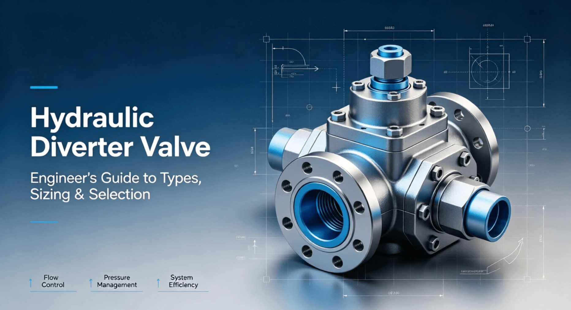
A hydraulic diverter valve redirects pump flow from one circuit path to another. It selects between two outlets while blocking the unused port. You feed one inlet, and the valve routes flow to outlet A or outlet B.
Most diverters use a sliding spool inside a machined bore. The spool has lands and grooves that align with internal ports. Shifting the spool changes which port connects to the inlet.
Diverter valves differ from directional control valves in intent. A DCV reverses a single actuator, extending then retracting a cylinder. A diverter chooses between two separate circuits. The hardware overlaps, but the application drives sizing and port logic.
How a Hydraulic Diverter Valve Works
Flow enters the inlet port under pump pressure. The spool sits in one of two stable positions. In position A, internal passages connect inlet to port A and block port B.
Shifting the spool to position B redirects flow. Port A closes, and port B opens to the inlet. The return path from the inactive circuit also routes back to tank through the valve.
Actuation methods move the spool. A manual lever pushes the spool directly. A solenoid coil pulls a plunger that pilots the spool. Hydraulic pilot pressure shifts larger spools where solenoids lack force.
Spring return brings the spool back to a default position when you release the actuator. Detent mechanisms hold the spool in place without continuous force. Choose detent for set-and-forget circuits and spring return for momentary selection.
Types of Hydraulic Diverter Valves
Manual Lever Diverter Valves
Manual diverters use a hand lever connected to the spool. The operator flips the lever to switch circuits. These valves suit low-cycle applications where an operator stands nearby.
Typical ratings run 210 to 350 bar with flows from 20 to 80 L/min. Bodies use cast iron or ductile iron. Ports follow SAE J1926 or ISO 6149 for mobile equipment.
Solenoid-Operated Diverter Valves
Solenoid diverters use an electric coil to shift the spool. A 12V or 24V DC coil suits mobile equipment. Industrial versions use 24V DC or 110/230V AC.
Response time lands between 15 and 60 ms, depending on spool mass and pilot design. Wet-pin coils run cooler and last longer than dry-pin types. Add a surge suppressor across the coil to protect upstream electronics.
Pilot-Operated Diverter Valves
Pilot-operated diverters use hydraulic pressure to move a large main spool. A small solenoid or manual valve routes pilot flow. The main spool handles high flow that a direct solenoid cannot move.
These valves suit flows above 100 L/min and pressures up to 420 bar. Pilot ratio and drain routing matter as much as the main spool. Always plumb the case drain to tank below fluid level.
Flow Divider Used as a Diverter
A flow divider splits pump flow between two circuits in parallel. Some engineers use a selectable divider when both proportional split and full divert matter. Note the difference. A true diverter sends all the flow one way or the other. A divider sends a fixed proportion to each circuit.
Key Specifications of Hydraulic Diverter Valve
| Spec | Mobile Diverter | Industrial Diverter |
|---|---|---|
Pressure |
210 to 350 bar |
350 to 420 bar |
Flow |
20 to 80 L/min |
80 to 300 L/min |
Voltage |
12/24 V DC |
24 V DC, 110/230 V AC |
Ports |
SAE J1926, ISO 6149 |
ISO 4401/CETOP, ISO 6149 |
Cleanliness |
ISO 4406 19/17/14 |
ISO 4406 18/16/13 |
Mounting |
In-line, cartridge |
Subplate, manifold |
Pressure rating sets the upper safe working pressure. Always derate 15 to 25 percent for shock loads. Flow rating matters more than pressure for diverter sizing because excess velocity washes out the spool.
Spool configuration drives the circuit behavior. A 2-position valve diverts between A and B only. A 3-position valve adds a center position that blocks, floats, or dumps both ports to tank.
Diverter vs Directional Control Valve vs Flow Divider
These three terms overlap, and suppliers use them loosely. The distinction matters when you specify parts.
A directional control valve reverses an actuator. A 4/3 DCV extends and then retracts a cylinder. The diverter selects between two circuits. A 4/2 diverter sends pump flow to circuit A or circuit B, not both.
A flow divider splits the flow proportionally. A 50/50 divider sends half the pump flow to each circuit at the same time. A diverter sends all flow to one circuit. Use a divider when both circuits move together. Use a diverter when only one moves at a time.
Selection Guide
Start with the circuit you want to select from. List the pump flow, the working pressure, and the cycle rate. Then match these against valve ratings.
Pick manual actuation for low-cycle mobile circuits. Pick solenoid actuation when an operator cannot reach the valve or when a controller drives the sequence. Pick pilot operation above 100 L/min.
Check the spool configuration. A 2-position valve diverts between A and B only. A 3-position valve adds a center position that can block both, float both, or route both to the tank.
Verify port standards against your hose fittings. SAE J1926 and ISO 6149 look similar but do not interchange. Mixing them causes leaks and damaged threads.
Sizing Math
Size the diverter for flow first, pressure second. Velocity through the valve body should stay under 6 m/s for continuous duty. Higher velocity erodes the spool and heats the oil.
Use this formula for flow velocity. v = Q x 21.22 / d squared. Q is flow in L/min, and d is port diameter in mm. For 60 L/min through a 12 mm port, v works out to 8.8 m/s. That exceeds the limit, so step up to a 16 mm port.
Pressure drop across the valve wastes energy and heats the oil. Most diverter catalogs list delta P at a reference flow. Scale it with the square of flow. If the catalog lists 2 bar at 40 L/min, expect 8 bar at 80 L/min.
Check case drain flow on pilot-operated types. Continuous drain above 3 to 5 L/min signals worn pilot seals. Log the drain flow during commissioning so you have a baseline.
Common Applications
Log Splitters
A log splitter uses a diverter to switch the cylinder between extension and retraction. Manual lever diverters dominate here. Cycle counts run high, so pick a detent model with a hard-wearing spool.
Loader Buckets
Tractor loaders use a diverter to select between lift and tilt circuits from a single joystick. Solenoid diverters let the operator switch without taking a hand off the joystick. Match the coil voltage to the vehicle’s electrical system.
Agricultural Implements
Three-point hitch implements often need a remote circuit beyond the hitch. A diverter splits the remote line between two functions. ISO 6149 ports and a 19/17/14 cleanliness target fit this duty.
Industrial Multi-Circuit Machines
Stationary machines run one pump into several stations. An industrial diverter on a CETOP subplate feeds a clamp, a press, and an ejector in sequence. Use 18/16/13 cleanliness and a pressure line filter ahead of the valve.
Installation and Plumbing
Mount the valve where an operator or service tech can reach it. In-line bodies are installed in the hose run. Subplate types bolt to a manifold and use O-rings to seal the ports.
Route the case drain below the tank fluid level. Above-level drains pull air and cause cavitation. Size the drain line for at least twice the expected drain flow.
Add a relief valve downstream of the diverter. When the spool shifts, the trapped column of oil between the valve and the actuator can spike. A cross-port relief absorbs that shock.
Bleed air from the valve before you pressurize the system. Trapped air makes the spool jump and shift erratically. Run the pump at low pressure and cycle the valve a few times.
Common Problems and Troubleshooting
| Symptom | Likely Cause | Action |
|---|---|---|
Spool will not shift |
Contamination, bent actuator rod |
Flush, inspect rod |
Sluggish shift |
Cold oil, wrong viscosity |
Check ISO VG grade |
Internal leakage |
Worn spool bore |
Re-hone or replace |
Coil burnout |
Wrong voltage, stuck spool |
Match voltage, free spool |
Erratic detent |
Broken spring, debris |
Replace detent kit |
Pressure spike on shift |
No cross-port relief |
Add relief downstream |
Contamination causes most diverter failures. A single hard particle wedged between the spool and the bore scores the surface. Once scored, the bore leaks and the spool sticks.
Cold oil also slows the shift. Most mobile systems run ISO VG 32 or 46 hydraulic oil. Check the viscosity grade against your operating temperature before you blame the valve.
Maintenance
Pull an oil sample every 500 hours for mobile equipment, every 2000 hours for industrial. Target ISO 4406 19/17/14 for mobile and 18/16/13 for industrial. A drift toward 21/19/16 means the filter needs attention.
Log spool shift time during planned downtime. A shift that slows from 30 ms to 80 ms warns of build-up before it fails. Trend the data, not just the single reading.
Replace solenoid coils in pairs if one fails early. The second coil usually follows within weeks. Keep a spare on the shelf rather than ordering after the second failure.
Inspect the detent mechanism when you service the valve. A worn detent spring lets the spool drift under shock. Replace the detent kit before the spool loses its position in service.
FAQ
What is a hydraulic diverter valve used for?
A hydraulic diverter valve redirects pump flow from one circuit to another. It selects between two outlets while blocking the unused port, so a single pump can feed multiple actuators in sequence. Common uses include log splitters, loader buckets, and agricultural implements.
How does a hydraulic diverter valve work?
The valve uses a sliding spool inside a machined bore. In one position, internal passages connect the inlet to port A. Shifting the spool redirects flow to port B while port A returns to tank. A manual lever, solenoid, or hydraulic pilot moves the spool.
What is the difference between a diverter valve and a directional control valve?
A directional control valve reverses a single actuator, extending then retracting a cylinder. A diverter selects between two separate circuits. The hardware overlaps, but the application drives sizing and port logic. A 4/2 diverter sends flow to circuit A or circuit B, not both.
What is the difference between a diverter valve and a flow divider?
A diverter sends all pump flow to one circuit or the other. A flow divider splits flow proportionally between two circuits at the same time. Use a diverter for sequential operation. Use a divider when both circuits must move together.
How do I size a hydraulic diverter valve?
Size for flow first. Keep port velocity under 6 m/s for continuous duty using v = Q x 21.22 / d squared. Then check the pressure rating and derate 15 to 25 percent for shock loads. Verify the case drain flow on pilot-operated types.
Why is my hydraulic diverter valve sticking?
Contamination is the most common cause. A hard particle wedged between the spool and bore scores the surface. Pull an oil sample and target ISO 4406 19/17/14 for mobile or 18/16/13 for industrial. Cold oil or wrong viscosity also slows the shift.
Should I choose a manual or solenoid diverter valve?
Use a manual lever for low-cycle circuits where an operator stands nearby. Use a solenoid when the operator cannot reach the valve or when a controller drives the sequence. Pick pilot operation above 100 L/min or 350 bar.
Conclusion
A hydraulic diverter valve solves a specific circuit problem: how to send one pump’s flow to one of two circuits. Get the type right, and the rest follows. Pick a manual for low-cycle mobile work. Pick a solenoid for electric control. Pick a pilot operation for high flow.
Size the valve for port velocity, not just pressure. Keep flow under 6 m/s for continuous duty. Add a cross-port relief to absorb shift spikes. Plumb the case drain below the tank fluid level on pilot-operated types.
Hold the oil clean. ISO 4406 19/17/14 for mobile and 18/16/13 for industrial keeps the spool shifting fast and the bore leak-free. Track the shift time and the drain flow, and you catch wear before it becomes downtime.