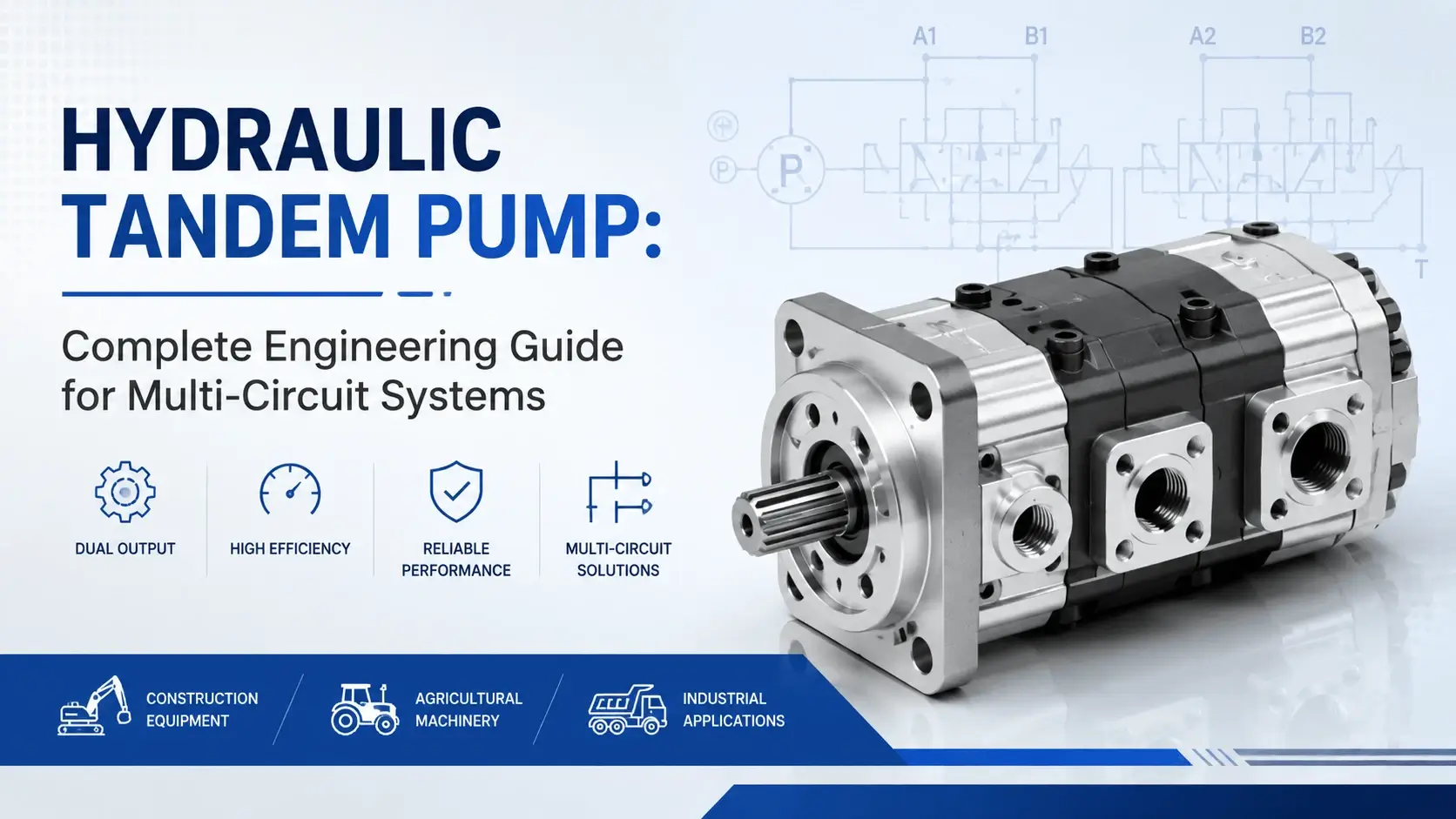
Hydraulic Tandem Pump: Complete Engineering Guide for Multi-Circuit Systems

Hydraulic Tandem Pump- Complete Engineering Guide for Multi-Circuit Systems

Table of Contents

Many machines need more than one hydraulic circuit. An injection molding unit requires high pressure for clamping and high flow for injection. A press brake needs force for bending and speed for positioning. Running two separate pumps takes space, costs more, and adds complexity. A hydraulic tandem pump solves this problem by mounting two pump sections on one shaft.
 
This guide covers how these pumps work, when to specify them, how to size them correctly, and what goes wrong in service. The information comes from field experience with tandem units in plastics machinery, metal forming equipment, and mobile hydraulic applications.

What is a Hydraulic Tandem Pump?

A hydraulic tandem pump combines two pump sections (stages) on a common input shaft. Each stage has its own inlet and outlet ports. The stages operate at the same speed because they share the shaft, but they can deliver different flows and pressures to separate hydraulic circuits.
 
The most common configuration pairs a large-displacement gear pump with a smaller gear or piston pump. The large section typically handles low-pressure, high-flow functions like rapid approach or clamp closing. The smaller section delivers lower flow at higher pressure for precision work or holding force.
 
Think of it as two pumps in one housing. You get the functionality of independent circuits without installing two complete pumping units with couplings, alignment fixtures, and additional mounting brackets.

How Tandem Pumps Work

The input shaft connects directly to the first pump section. In a gear tandem unit, this drives the main gear set. The shaft continues through an intermediate plate into the second section, where it drives another gear set or a piston rotating group.
 
Both sections rotate together. Speed is identical. Flow from each stage depends on its displacement per revolution multiplied by shaft speed. A 63 cc/rev gear section turning 1450 rpm delivers roughly 91 L/min. A 20 cc/rev piston section on the same shaft delivers about 29 L/min at the same speed.
 
Pressure independence matters here. Stage 1 might run at 140 bar while stage 2 operates at 250 bar. The circuits remain hydraulically isolated from each other. Only mechanical power transfers through the shared shaft.
 
One detail worth remembering: back pressure on the outlet of the second stage adds load to the shaft. This affects bearing life and overall efficiency. Proper sizing accounts for the combined torque requirement.

Main Components

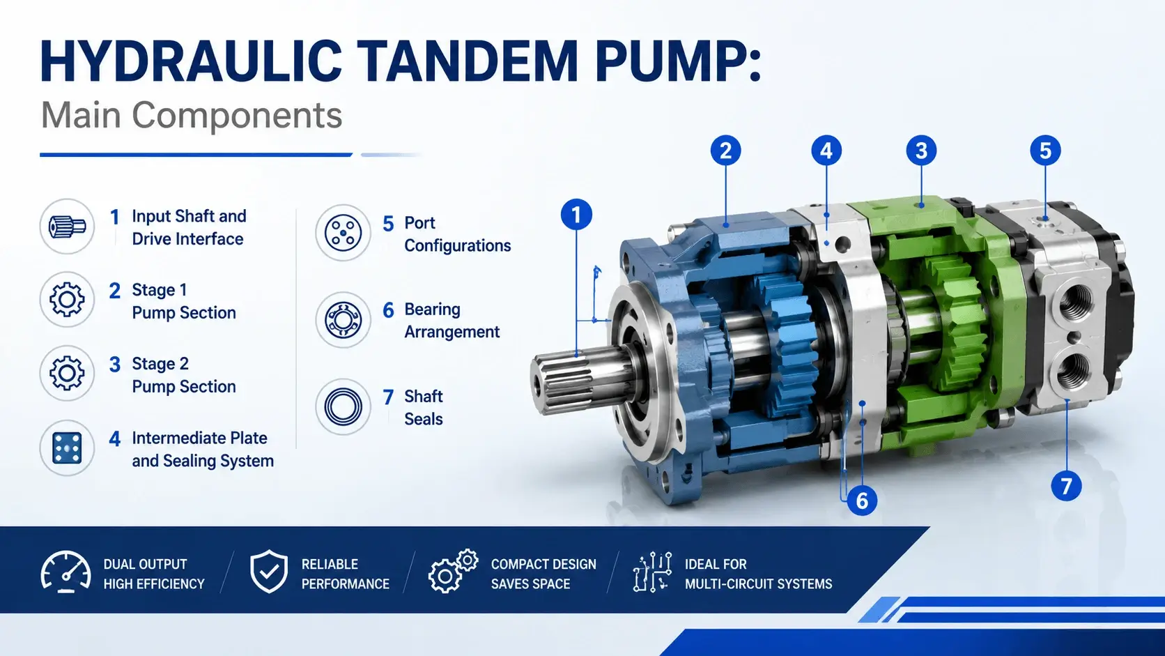
Main Components of hydraulic tandem pump
Understanding the parts helps with specification, maintenance, and troubleshooting.

Input Shaft and Drive Interface

The shaft accepts coupling connection to your motor or engine. SAE J-type mounts are standard on most industrial tandems. The shaft must handle combined torque from both stages plus any external axial or radial loads from the coupling misalignment.

Stage 1 Pump Section

Usually the larger displacement unit. In gear tandems, this is typically a straight-tooth or helical gear set with cast iron housing. Displacement ranges from 32 cc/rev to 250 cc/rev for common industrial sizes. Pressure ratings reach 250-280 bar for standard gear sections.

Stage 2 Pump Section

Often smaller displacement, sometimes a different pump type. Gear-gear tandems are common for cost-sensitive applications. Gear-piston combinations suit applications needing higher pressure (up to 350 bar) from the second stage. The piston section uses valve plate porting and a rotating cylinder block with pistons stroking against a swash plate.

Intermediate Plate and Sealing System

The plate separates the two stages while allowing shaft passage. Sealing between stages prevents cross-leakage of oil at different pressures. Gasket quality matters here. A failed intermediate seal causes internal leakage that looks like low flow from one circuit but actually loses oil between stages.

Port Configurations

Each stage has dedicated inlet and outlet ports. SAE flange ports (SAE J518) handle larger flows above 80 L/min. Threaded ports (BSP or metric) work for smaller flows. Port location varies by manufacturer: side ports, rear ports, or top-mounted manifolds are all available.

Bearing Arrangement

Tandem pumps carry more load than single pumps. The bearings see combined radial and axial forces from both pumping stages plus drive coupling reaction forces. Quality units use tapered roller bearings or angular contact ball bearings rated for the combined L10 life calculation.

Shaft Seals

Lip seals or mechanical seals prevent oil leakage along the shaft. High-pressure shaft seals on the outlet side must contain maximum system pressure plus any pressure spikes. Low-pressure inlet seals keep dirt out and oil in.

Tandem Pump Configurations

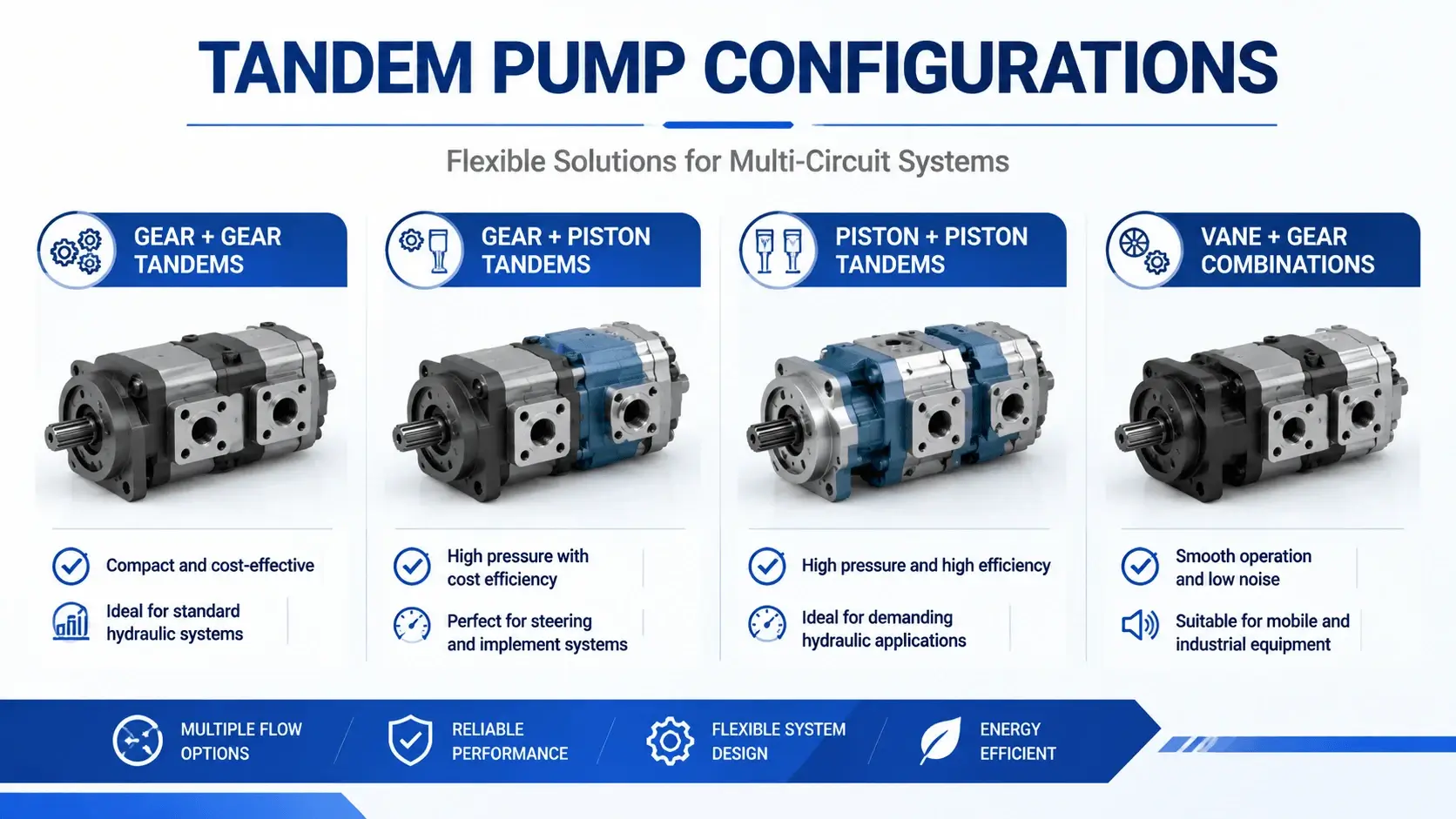
Tandem Pump Configurations
Different combinations serve different applications. Choosing the right configuration affects performance, cost, and service life.

Gear + Gear Tandems

The most economical option. Both stages are external gear pumps. Pressure capability tops out around 250-280 bar. Good for general industrial applications where both circuits operate below this range. Noise levels are moderate. Efficiency ranges from 80-88% depending on pressure and speed.

Gear + Piston Tandems

A popular configuration for mixed requirements. The gear section handles high-flow, lower-pressure duties. The piston section provides precision flow at pressures up to 350 bar. This suits injection molding machines where the gear pump moves the injection screw fast at low pressure, and the piston pump builds packing and holding pressure.
Cost is higher than gear-gear. The piston section requires cleaner oil (ISO 4406 code 17/15/12 or better) and regular filter maintenance. But you get better efficiency (90-95% in the piston stage) and finer control.

Piston + Piston Tandems

Used when both circuits need high pressure or precise flow control. Common in servo-hydraulic press systems and testing machines. Most expensive configuration. Requires excellent filtration and temperature control. Total efficiency can exceed 92% when properly maintained.

Vane + Gear Combinations

Less common but useful for specific cases. Vane pumps offer quiet operation and good mid-range performance. Paired with a gear pump, they serve applications where noise is a concern but some circuits still need simple robust pumping action.
 

Advantages of Using Tandem Pumps

Engineers specify hydraulic tandem pump units for several concrete reasons.

Space Savings

A typical tandem occupies 30-40% less floor space than two single pumps with coupling and baseplate. On a machine with limited footprint, like a mobile equipment power unit or a compact press, this matters. The envelope dimensions usually run 1.3-1.6 times the length of a single pump versus 2.2-2.5 times for two separate units.

Installed Cost Reduction

Compare a tandem assembly against two singles: one motor, one coupling, one mount, one alignment procedure, less plumbing. Material cost savings range from 15-25% depending on configuration. Labor savings during assembly add to this. For OEMs building hundreds of machines per year, the difference adds up.

Simplified Alignment

Only one shaft alignment exists between motor and pump. Two single pumps require motor-to-pump-1 alignment plus pump-1-to-pump-2 alignment via coupling. Each alignment introduces potential error. A hydraulic tandem pump eliminates the inter-pump alignment entirely.

Reduced Plumbing

Fewer fittings, hoses, and adapters mean fewer leak points. Each eliminated connection removes a potential failure mode. In systems running 24/7, reliability improvement from reduced plumbing alone justifies the tandem approach in many cases.

Single Drive Source

One motor or engine drives both circuits. Control simplifies. You start one motor instead of sequencing two. Electrical panel complexity drops. Emergency stop logic becomes straightforward.

Limitations and Trade-offs

No component fits every application. Tandem pumps have constraints worth understanding before specification.

Back-Pressure Effects on Stage 2

The second stage operates in the shadow of the first. When stage 1 outlet pressure runs high, shaft deflection increases slightly. This changes internal clearances in stage 2. The effect is small but measurable: 2-5% efficiency loss at max differential pressure across both stages. High-performance designs minimize this with stiff shafts and optimized bearing placement.

Thermal Management Challenges

Two pumping stages in one housing generate concentrated heat. Oil temperature rises faster than in separated pump installations. You need adequate reservoir capacity (minimum 3x total flow rate per minute) and possibly a heat exchanger for continuous-duty applications above 75% of rated power.

Single-Point Failure Risk

If the input shaft bearing fails, both circuits go down. With two independent pumps, one can continue running if the other fails. For critical processes requiring redundancy, consider whether this risk is acceptable. Some users install a backup tandem or maintain a spare on shelf.

Maintenance Access Constraints

Working on stage 2 requires dealing with stage 1 first in many designs. Disassembly sequence matters. Some configurations allow independent servicing; others demand full teardown. Check the manual before assuming quick access to the rear section.

Sizing Flexibility Limits

You cannot always get exactly the displacement combination you want. Manufacturers offer standard pairings: 32+10, 50+16, 63+20, 100+25 cc/rev are common. Custom combinations exist but carry longer lead times and higher costs. Your circuit calculations may require compromise between ideal and available.

Industrial Applications

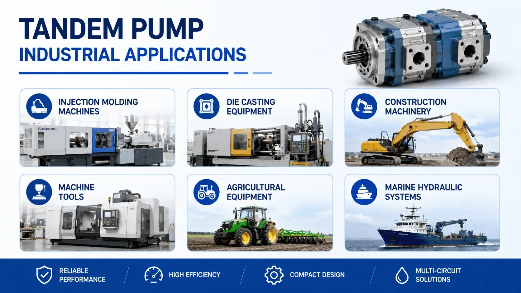
tandem pump Industrial Applications
Tandem pumps appear wherever machines need multiple hydraulic functions from a compact power source.

Injection Molding Machines

The classic application. Large gear pump (100-200 cc/rev) rapidly moves the injection screw forward at low pressure for mold filling. Smaller piston pump (16-40 cc/rev) builds packing pressure up to 2000-2500 psi (140-175 bar) and holds it during cooling. Cycle after cycle, the hydraulic tandem pump delivers the right flow at the right pressure from each section.

Die Casting Equipment

Similar duty cycle. Clamp closure needs high flow at moderate pressure. Injection stroke requires controlled flow at very high pressure (280-350 bar). A gear-piston tandem matches this profile well. Die cast runs are often continuous, so thermal management and filtration become critical.

Construction Machinery

Excavators use tandem arrangements for boom/dipper/stick circuits plus pilot pressure or swing circuits. The main pump sections (often variable displacement in modern machines) handle digging forces. A smaller gear section maintains constant pilot pressure for valve actuation. Compact packaging fits within the tight engine compartment envelope.

Machine Tools

CNC machining centers sometimes use hydraulics for spindle clamping, tool changer actuation, and pallet rotation. A small hydraulic tandem pump (total displacement under 40 cc/rev) serves all three circuits from one 3-phase motor mounted inside the cabinet. Clean, quiet, space-efficient.

Agricultural Equipment

Tractors with front loaders and rear implements benefit from tandem setups. One circuit powers the loader lift and tilt. Another handles rear hitch position and draft control. A gear-gear tandem handles both functions economically in a harsh environment where dust and temperature extremes challenge component life.

Marine Hydraulic Systems

Deck cranes, winches, and steering gear on vessels use tandems for main function plus auxiliary circuits. Salt air exposure demands corrosion-resistant materials. The compact size helps in crowded engine rooms. Classification society rules (ABS, DNV, Lloyd’s) may dictate specific certification requirements for the pump assembly.

Selection Guide

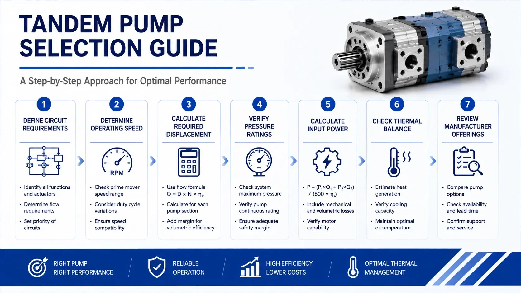
tandem pump selection guide

Choosing the right hydraulic tandem pump requires systematic calculation. Follow this procedure.

Step 1: Define Circuit Requirements

List each circuit separately:

Circuit A (main function):

  • Maximum flow required: Qa_max = 120 L/min
  • Working pressure: Pa = 210 bar
  • Duty cycle: 60% of time at full pressure

Circuit B (auxiliary function):

  • Maximum flow required: Qb_max = 35 L/min
  • Working pressure: Pb = 175 bar
  • Duty cycle: 40% of time at full pressure

Step 2: Determine Operating Speed

Your motor or engine dictates pump speed. Electric motors commonly run at 1450 rpm (4-pole, 50 Hz) or 1750 rpm (4-pole, 60 Hz). Diesel engines vary widely. Confirm the actual speed at your expected load, not just nameplate synchronous speed.

Assume 1450 rpm for this example.

Step 3: Calculate Required Displacement

Displacement per revolution equals flow divided by speed (with volumetric efficiency factor):

For Circuit A:Va = Qa_max / (speed × ηv) = 120 / (1450 × 0.92) = 0.090 L/rev = 90 cc/rev

Select standard size: 100 cc/rev (next standard size up)

For Circuit B:Vb = Qb_max / (speed × ηv) = 35 / (1450 × 0.92) = 0.026 L/rev = 26 cc/rev

Select standard size: 25 or 32 cc/rev (25 cc/rev gives slight margin; 32 cc/rev gives more margin but wastes some flow as relief heat)

Choose 25 cc/rev for efficiency.

Step 4: Verify Pressure Ratings

Check that each selected pump section meets or exceeds the required pressure:

  • 100 cc/rev gear section: rated 250 bar > 210 bar required. OK.
  • 25 cc/rev gear section: rated 250 bar > 175 bar required. OK.

If Circuit B needed 280 bar, you would select a piston section for stage 2 instead of gear.

Step 5: Calculate Input Power

Total hydraulic power determines motor sizing:

Pa_hyd = (Qa × Pa) / 600 = (120 × 210) / 600 = 42 kWPb_hyd = (Qb × Pb) / 600 = (35 × 175) / 600 = 10.2 kWTotal = 52.2 kW

Account for overall efficiency (typically 83-87% for gear-gear tandem at operating point):

P_input = 52.2 / 0.85 = 61.4 kW

Select a 75 kW motor (standard next size up with margin).

Step 6: Check Thermal Balance

Calculate heat generation:

Heat = P_input − P_hyd_useful = 61.4 − 52.2 = 9.2 kW

Reservoir must dissipate this heat. Rule of thumb: reservoir volume should be 3-5 times total flow per minute. Total flow here is 155 L/min. Minimum reservoir: 465 liters. If ambient temperature is high or duty cycle is continuous, add a water-oil or air-oil cooler sized for 10-12 kW rejection.

Step 7: Review Manufacturer Offerings

Now you know what you need: 100 + 25 cc/rev, 250 bar, 1450 rpm, SAE J mounting. Contact manufacturers with these specs. Compare lead time, price, local support availability, and warranty terms. A hydraulic tandem pump from a reputable supplier with service network access reduces long-term ownership risk.

Troubleshooting Common Issues
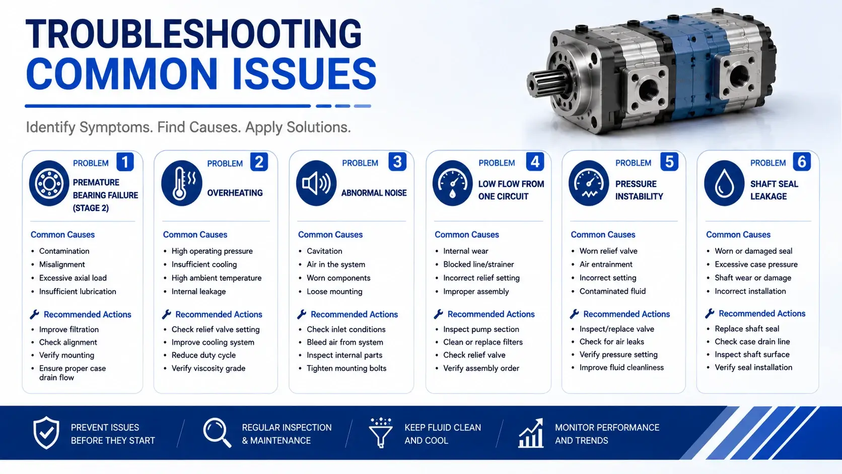
Troubleshooting Common Issues

Field problems with tandem pumps follow patterns. Recognizing these patterns speeds diagnosis.

Problem 1: Premature Bearing Failure (Stage 2)

Symptoms: Noise increases gradually over weeks. Metal particles appear in the filter element. Eventually, shaft locks or seizes.

Common cause: Coupling misalignment puts radial load on the input shaft. The cantilever effect amplifies at the distant stage 2 bearing. A misalignment of 0.15 mm TIR at the coupling can produce 0.05 mm deflection at the rear bearing, cutting L10 life by 60-70%.

Fix: Laser-align motor and pump to within 0.05 mm TIR angular and offset. Check coupling condition. Replace worn elastomer elements. Use spacer couplings for longer tandem units to reduce overhang moment.

Problem 2: Overheating

Symptoms: Oil temperature exceeds 60°C within 30 minutes of startup. Pump case feels too hot to touch comfortably.

Causes:

  • Reservoir undersized for the total flow (both stages combined)
  • Relief valves set too close to working pressure, causing constant overflow
  • Internal leakage increased due to wear (check flow at low pressure vs. rated pressure)
  • Cooler plugged or fan failure (if equipped)
  • Viscosity too low for operating temperature (oil thinning reduces lubrication film)

Diagnostic steps: Measure flow from each stage separately using a flow meter. Compare to catalog values at same speed and pressure. A drop greater than 15% indicates wear. Check relief valve settings with calibrated gauge. Verify cooler operation.

Problem 3: Abnormal Noise

Whining or screaming noise suggests cavitation. Air entrainment causes a rattling or grinding sound.

Cavitation causes:

  • Inlet restriction (collapsed hose, clogged strainer, undersized line)
  • Oil viscosity too high for cold start
  • Inlet pressure below -0.3 bar (vacuum) at pump port

Air entrainment causes:

  • Shaft seal leak sucking air in (common on inlet-side seals)
  • Return line above oil level causing aeration
  • Low reservoir level exposing inlet pipe

Fix each cause directly. Replace restricted lines. Preheat oil in cold climates. Repair leaking seals. Submerge returns below minimum oil level.

Problem 4: Low Flow from One Circuit

When Circuit A works normally, but Circuit B has weak or slow action, the issue isolates to stage 2 or its circuit.

Check sequence:

  1. Verify stage 2 relief valve setting (may have drifted low)
  2. Check for external leak in circuit B plumbing
  3. Measure stage 2 flow with a flow meter
  4. If flow is low at low pressure, internal wear is likely
  5. If flow is normal at low pressure but drops at pressure, check intermediate plate sealing

Internal leakage between stages through a failed intermediate seal mimics stage 2 weakness. The oil goes somewhere, just not where you want it.

Problem 5: Pressure Instability

Oscillating pressure in one circuit while the other remains steady usually indicates a problem in that specific stage or its controls.

Possible causes:

  • Worn pressure compensator (if variable displacement)
  • Trapped air in the circuit (needs bleeding)
  • Accumulator precharge incorrect (if fitted)
  • Valve spool sticking due to contamination

Isolate the affected circuit systematically. Swap relief valves between circuits if possible to rule out valve issues.

Problem 6: Shaft Seal Leakage

Oil dripping from the shaft end indicates seal failure. Minor weeping (a few drops per hour) warrants monitoring. Steady streaming requires immediate attention.

Causes:

  • Normal wear after 8,000-12,000 hours of operation
  • Shaft surface scored or corroded
  • Excessive case pressure (drain line blocked or restricted)
  • Misalignment-induced shaft eccentricity loading the seal lip

Replace seal and inspect shaft condition. Polish light scoring with fine emery cloth. Deep scores require shaft replacement or sleeve installation. Verify case drain line is open and unrestricted.

Maintenance Protocol

Preventive maintenance extends hydraulic tandem pump life significantly. Follow this schedule.

Daily Checks (Operator Level)

  • Visual inspection for leaks at all ports and shaft seal
  • Listen for abnormal noise (cavitation sounds, bearing whine)
  • Check oil level in reservoir
  • Note oil color and clarity (milky equals water, dark equals oxidation)
  • Observe case temperature (should be warm, not hot enough to sizzle droplet)

Weekly Checks (Technician Level)

  • Check and record system pressures at working conditions
  • Inspect filter differential indicator; change element if indicated
  • Sample oil for analysis (particle count, moisture, viscosity)
  • Tighten mounting bolts to specified torque
  • Verify cooler operation (airflow or water flow)

Monthly Checks (Engineer Level)

  • Laser verify shaft alignment (document readings)
  • Test relief valve cracking pressure
  • Measure flow from each stage at operating pressure
  • Compare to baseline data taken at commissioning
  • Inspect coupling element for cracks or hardening
  • Check hose condition at all connections

Annual Overhaul (or per 8,000-10,000 hours)

  • Remove pump for bench inspection
  • Measure internal clearances (gear tooth wear, piston/cylinder clearance)
  • Replace all seals (shaft seals, O-rings, gaskets)
  • Inspect bearings for play or race damage
  • Replace bearings proactively if near calculated L10 life
  • Rebuild with new intermediate plate gasket
  • Record measurements for trend analysis

Storage Procedures

If removing pump from service for extended period:

  • Drain oil completely
  • Flush with light oil if contaminated
  • Fill with ISO VG 32 corrosion-inhibiting oil
  • Rotate shaft by hand monthly to re-distribute oil film
  • Seal all ports with caps or plugs
  • Store indoors, horizontal position, off the floor

Store in a climate-controlled environment if possible. Temperature swings cause condensation inside the housing, leading to internal rust during long storage periods.

FAQ

What is a hydraulic tandem pump?

A hydraulic tandem pump mounts two pump sections on a single rotating shaft. Each section has its own inlet and outlet ports and supplies a separate hydraulic circuit. Both sections turn at the same speed but can deliver different flows and pressures independently.

How does a tandem pump differ from two single pumps?

A tandem integrates both sections in one housing with one input shaft. Two single pumps require a coupling between them, double the mounting space, separate alignment procedures, and more plumbing. The tandem saves space, reduces parts count, and simplifies installation.

What are the main advantages of tandem pumps?

Primary benefits include 30-40% space savings compared to two single pumps, 15-25% lower installed cost, simplified alignment (only one coupling), fewer leak points from reduced plumbing, and single-motor drive reducing electrical complexity.

Can the two stages operate at different pressures?

Yes. Each stage connects to a separate hydraulic circuit with its own relief valve. Stage 1 might run at 140 bar while stage 2 operates at 250 bar. The circuits remain hydraulically isolated. Only mechanical power transfers through the shared shaft.

What is the typical pressure range for tandem pumps?

Gear-gear tandems typically handle 210-280 bar. Gear-piston combinations extend this to 350 bar in the piston stage. Piston-piston tandems can reach 350-420 bar. Actual rating depends on manufacturer, displacement size, and duty cycle.

How do I size a tandem pump for my application?

Calculate required flow for each circuit separately. Divide each flow by pump speed and volumetric efficiency to get displacement per stage. Round up to standard sizes offered by manufacturers. Verify pressure ratings meet or exceed circuit requirements. Size motor for combined power plus 15-20% margin.

What are common failure modes?

Premature bearing failure (usually from misalignment), overheating (inadequate cooling or internal wear), cavitation (inlet restrictions), seal leakage (wear or excessive case pressure), and low flow from one stage (internal wear or intermediate seal failure).

How often should I service a tandem pump?

Daily visual checks by operators. Weekly pressure and filter checks by technicians. Monthly alignment verification and flow testing. Major overhaul every 8,000-10,000 operating hours or annually, whichever comes first. Adjust interval based on operating severity and oil analysis results.

What maintenance does a tandem pump need?

Keep oil clean (ISO 4406 17/15/12 or better for piston stages), cool (below 60°C), and at correct viscosity (ISO VG 46 or 68 for most applications). Monitor alignment quarterly. Replace seals and bearings proactively based on calculated life, not just on failure. Document all measurements for trend analysis.

Conclusion

A hydraulic tandem pump offers a proven solution for multi-circuit hydraulic systems where space, cost, and simplicity matter. The technology has served industry for decades in injection molding, die casting, construction equipment, and countless other applications.

Success depends on proper selection, careful installation (especially alignment), and consistent maintenance. Understand the trade-offs: back-pressure effects, thermal concentration, and single-point failure risk. Design around them rather than being surprised by them later.

If you are evaluating a hydraulic tandem pump for a new project or retrofit, start with accurate circuit requirements, follow the sizing procedure outlined above, and consult with suppliers who understand your application. The right specification avoids costly field problems and delivers reliable service over the pump’s design life.

Related Articles

Scroll to Top
Shoot Us An Email

Professional Manufacturer