
Introduction
A closed loop hydraulic system moves oil between a pump and a motor. The full flow never returns to a tank. That closed-circulation lets one variable displacement pump drive a motor in both directions. It controls motor speed precisely and holds it stalled under load. You find these circuits on excavator travel drives, winches, marine thrusters, and mill drives.
This guide breaks down how a closed-loop circuit actually works. It covers the charge pump, the hot oil shuttle, and the crossport relief valves that protect the loop. It also gives you sizing math, troubleshooting steps, and field maintenance numbers drawn from machines running 350-420 bar daily.
What is a Closed Loop Hydraulic System
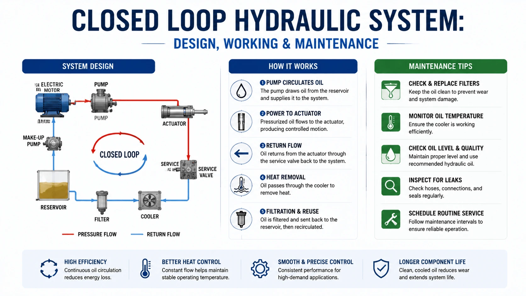
A closed loop hydraulic system circulates pressurized oil in a continuous loop. Oil runs from a pump outlet, through a hydraulic motor, and back to the pump inlet. People also call this a hydrostatic transmission.
Only a small fraction of the oil leaves the loop. That fraction covers internal leakage and heat removal, and a charge pump replaces it continuously.
The defining trait is the return path. In an open loop, spent oil is dumped back into a reservoir before the pump draws it again. In a closed loop, the motor outlet connects straight to the pump inlet. This lets the pump reverse the motor by tilting its swashplate past center. No directional valve sits in the main line.
Typical closed-loop pressures run 350-420 bar continuous, with peaks near 480 bar on heavy mobile drives. Charge pressure sits much lower, usually 15-35 bar, just enough to keep the loop full and prevent cavitation.
How a Closed Loop Hydraulic System Works
Power flows in a tight circle. A variable displacement axial piston pump pushes oil out one high-pressure port and into one side of the motor. The oil turns the motor, then exits the other motor port and returns to the opposite pump port. The pump draws the return oil straight back in.
To reverse the motor, the operator or controller tilts the pump swashplate the other way. Oil then leaves the second port instead, and the motor spins backward. No directional control valve intervenes in the main flow path. Reversal feels instant because the oil column never has to refill a long line.
Internal leakage always steals some oil. Piston shoes, valve plates, and motor port plates all leak a few percent of rated flow past their clearances. A charge pump feeds makeup oil through two check valves. It runs off the main pump shaft or a separate gear pump. Each check valve opens to whichever loop side drops below the charge pressure.
That makeup keeps the loop full. It also flushes heat out. A hot oil shuttle valve senses the low-pressure side of the loop. It dumps a controlled slice of warm oil into the tank. The charge pump replaces that dumped volume with cool oil from the reservoir. A heat exchanger in the charge or return line rejects the heat.
Crossport relief valves sit between the two loop lines. If pressure spikes above the setpoint on either side, the valve cracks and bleeds flow to the opposite line. This protects the pump and motor during sudden overruns, like a loaded excavator braking on a slope.
Main Components of Closed Loop Hydraulic System
| Component | Function | Typical Specification |
|---|---|---|
Variable Displacement Piston Pump |
Drives the loop, reverses flow via swashplate |
Axial piston; 250-420 bar continuous; bi-directional |
Axial Piston Motor |
Converts loop flow and pressure to shaft torque |
Fixed or variable displacement; up to 480 bar peak |
Charge Pump |
Replenishes leakage, keeps loop pressurized |
Gear pump; 10-25% of main loop flow; 15-35 bar |
Replenishing Check Valves |
Feed charge oil to the low-pressure side |
Two check valves, one per loop line |
Crossport Relief Valves |
Limit pressure spikes on either loop side |
Cracking at 420-500 bar; integral to pump |
Hot Oil Shuttle (Flush) Valve |
Drains warm oil to tank for cooling |
Spools to low-pressure side; 10-30% of loop flow |
Heat Exchanger |
Rejects heat from charge/return flow |
Air or water cooled; sized to loop losses |
Servo Control |
Tilts pump swashplate for displacement |
Mechanical, hydraulic, or electro-hydraulic |
Case Drain Line |
Carries internal leakage to tank |
Must stay below 3-5 bar back-pressure |
Open Loop vs Closed Loop Hydraulic System
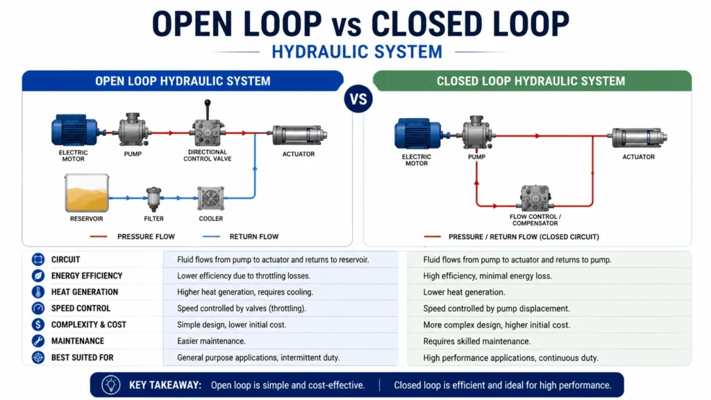
The two architectures solve different problems. Open loop suits actuators that need a large reservoir, multiple valves, and easy filtration. Closed loop suits continuous rotary drives where reversing, speed control, and compactness matter more.
| Factor | Open Loop | Closed Loop |
|---|---|---|
Return path |
Oil returns to tank each cycle |
Oil circulates pump-motor-pump |
Directional control |
Directional valve required |
Pump swashplate reverses flow |
Reservoir size |
Large, full system flow |
Small, only charge + flush volume |
Filtration access |
Easy, full return-line flow |
Limited; charge inlet and loop flush only |
Heat rejection |
Straightforward via tank |
Needs hot oil shuttle + heat exchanger |
Typical pressure |
Up to 350 bar |
350-480 bar |
Best fit |
Cylinders, multi-function machines |
Single rotary drive, travel, winch |
Choose open loop when you run many actuators off one pump bank. Choose closed loop when one drive needs precise bidirectional speed control at high pressure. Many machines run both: a closed loop for travel, open loop for boom and bucket.
Types of Closed Loop Hydraulic System
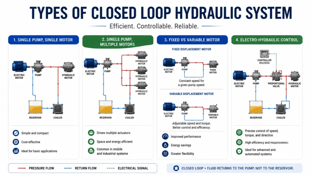
Single pump, single motor. The simplest layout. One variable pump drives one motor. Excavator travel drives and most winches use this. The pump reverses and varies displacement to control motor speed and direction.
Single pump, multiple motors. One pump feeds two motors through a divider or in parallel. Skid steer traction drives split flow between left and right wheels. Losing traction on one side shifts flow, so designers add flow dividers or use separate pumps per side.
Fixed vs variable motor. A variable displacement motor widens the speed-torque range. Low displacement gives high speed and low torque. High displacement gives low speed and high torque. Two-speed travel motors shift displacement internally for road travel versus digging.
Electro-hydraulic control. Modern closed loops use proportional valves to drive the pump servo piston. A controller maps joystick input to swashplate angle. This adds fine low-speed control and enables closed-loop speed feedback, common on precision winches and marine thrusters.
Key Specifications
| Parameter | Typical Range | Notes |
|---|---|---|
Continuous pressure |
350-420 bar |
Piston pump/motor rated |
Peak pressure |
up to 480 bar |
Crossport relief cracking |
Charge pressure |
15-35 bar |
Set above case drain back-pressure |
Charge pump flow |
10-25% of main flow |
Covers leakage + flush volume |
Case drain flow (healthy) |
2-5% of rated flow |
Rising flow signals wear |
Case drain back-pressure |
under 3-5 bar |
Exceeding this damages seals |
Loop flush flow |
10-30% of loop flow |
Hot oil shuttle dump volume |
ContentCleanliness target |
ISO 4406 18/16/13 |
Tighter than many open loops |
Port standard |
SAE J1926 / ISO 6149 |
O-ring face seal for high pressure |
Advantages
Closed-loop drives pack high power into a small package. The pump and motor handle 350-420 bar continuously, so a compact unit delivers serious torque. You avoid long high-pressure lines because the pump and motor sit close together.
Reversal needs no directional valve. Tilting the swashplate past center flips motor direction instantly. This removes a valve, its pressure drop, and its shift lag from the main circuit.
Speed control stays smooth across the full range. A variable pump varies flow from zero to the rated flow without throttling. The motor holds torque at any speed, including stall, without overheating a relief valve.
Energy efficiency ranks high. The pump delivers only the flow the motor needs. At idle, it strokes to near zero and draws little power. This beats an open loop that dumps excess flow over a relief at full pressure.
Disadvantages and Limitations
Heat is the constant enemy. Almost no oil returns to a tank to cool off. Internal leakage heats the trapped oil fast, so a hot oil shuttle and heat exchanger become mandatory, not optional. Undersized cooling trips overtemperature shutdowns within minutes of heavy load.
Contamination hurts closed loops more than open loops. You can only filter at the charge pump inlet and the flush return. A small dirt slug can score a piston shoe or stick a servo valve. You target ISO 4406 18/16/13, and you actually have to hold it.
Cost runs higher. Variable piston pumps, servo controls, charge circuits, and heat exchangers add price and complexity. A closed-loop travel drive costs more than an open-loop valve-and-motor setup doing the same job.
Reservoir access is poor. You cannot easily filter the full loop flow or sample oil mid-circuit. Diagnostics lean on charge pressure gauges and case drain flow meters instead of a simple tank sight glass.
Industrial Applications
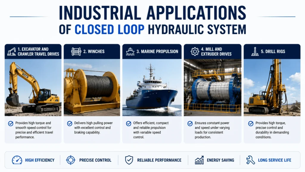
Excavator and crawler travel drives. The classic closed-loop use. A variable pump on each side drives a piston motor through a planetary track motor. Reversing the pump steers; mixing the two sides turns the machine.
Winches. Traction and crane winches need smooth payout, stall holding, and precise creep speed. A closed loop delivers all three. The hot oil shuttle keeps the brake and motor cool during long controlled descents.
Marine propulsion. Azimuth thrusters and waterjets run closed loop because the prime mover stays fixed while the drive turns. The loop transmits power through rotary unions without a gearbox in the rotating pod.
Mill and extruder drives. Plastic, rubber, and paper mills use closed loops to maintain tight speed regulation under varying loads. Variable motors extend the torque range across product grades.
Drill rigs. Top drives and rotary tables need full torque at near-zero speed and instant reversal. Closed loop hydrostatics provide that without slipping clutches.
Common Failure Modes
Charge pressure loss. If the charge pressure falls below the loop’s low-side pressure, the replenishing check valves stop feeding oil. The pump cavitates within seconds. Causes include a clogged charge filter, a worn charge pump, or a stuck charge relief valve. Check the charge pressure first on any sluggish or noisy loop.
Cavitation. Air bubbles collapsing inside the pump score the valve plate and piston shoes. You hear a rattling or whining sound under load. Root causes tie back to low charge pressure, restricted charge inlet, or high oil viscosity on cold starts.
Overheating. Loop temperature above 90 °C degrades oil fast and cooks seals. Usual culprits include an undersized or fouled heat exchanger, a stuck hot oil shuttle, or rising motor leakage. Monitor the case drain temperature as an early warning.
Contamination wear. Hard particles under 10 microns cause most closed-loop failures. They erode piston shoe clearances, which raises case drain flow and leakage heat. A cleanliness slip from 18/16/13 to 22/20/17 can halve pump life.
Servo control failure. A stuck or slow servo valve makes the pump respond erratically. The motor surges or refuses to reverse. The usual causes are contamination in the servo pilot circuit or low servo pressure.
Troubleshooting Guide
| Symptom | First Check | Likely Cause | Action |
|---|---|---|---|
Motor will not move |
Charge pressure gauge |
Charge pump failure or relief stuck |
Verify charge pressure at 15-35 bar; replace filter |
Loud whine under load |
Charge pressure + oil temp |
Cavitation from low charge or cold oil |
Warm oil; confirm charge flow; clean inlet |
Loop overheats (>90C) |
Hot oil shuttle + cooler |
Stuck shuttle or fouled heat exchanger |
Test shuttle spool; clean cooler; check case drain |
Slow or weak motor |
Case drain flow |
Internal leakage in pump or motor |
Measure case drain; over 10% means overhaul |
Motor surges or oscillates |
Servo pressure + response |
Sticky servo valve or low servo pressure |
Flush servo circuit; check servo filter |
Will not reverse |
Swashplate feedback |
Broken servo link or controller fault |
Inspect servo linkage; verify control signal |
Always start with charge pressure. It is the cheapest, fastest test, and it rules out half the possible faults in one reading.
Selection and Sizing Guide
Size the loop from the load back to the pump. Work in this order:
Find motor torque. Torque (Nm) equals displacement (cc/rev) times pressure (bar) times 0.0159. Pick a motor displacement that delivers the required torque at your chosen pressure, leaving a 10-15% margin below the relief setting.
Find motor speed and flow. Flow (L/min) equals displacement (cc/rev) times speed (RPM) divided by 1000. Add 3-5% for volumetric leakage.
Match the pump. Pump-rated flow must meet motor flow at the pump’s input speed. Pick a pump displacement so that pump flow equals motor flow at engine RPM.
Set pressure. Continuous pressure 350-420 bar covers most mobile drives. Set crossport relief 15-25 bar above your max working pressure.
Size the charge pump. Charge flow equals 10-25% of main loop flow, enough to cover leakage plus flush. Set charge relief to 15-35 bar, above the case drain back-pressure.
Size the heat exchanger. Reject the heat from loop losses. Estimate losses as 3-8% of transmitted power, then add flush return heat. Spec the cooler to hold loop oil under 80 °C at design ambient.
Maintenance Tips
Check charge pressure monthly. Connect a gauge at the charge test port. It should read 15-35 bar steady at idle. A drop over 5 bar from baseline means a clogged filter, weak charge pump, or leaking charge relief. Fix it before the loop cavitates.
Measure case drain flow quarterly. Catch case drain output for one minute at rated pressure. New units run 2-5% of rated flow. A reading above 10% flags worn piston shoes or a scored valve plate. Schedule an overhaul before the unit fails in service.
Hold oil cleanliness. Sample loop oil and target ISO 4406 18/16/13. Change the charge inlet filter on differential pressure, not just hours. A clogged charge filter starves the pump and starts the cavitation cascade.
Watch the loop temperature. Fit a sensor in the case drain line. Normal runs 65-80 °C. Above 90 °C, oil oxidizes, and seals harden. Investigate the cooler, the hot oil shuttle, and case drain flow together rather than chasing one symptom.
Service the hot oil shuttle. A stuck shuttle dumps too little warm oil, so the loop overheats. Or it dumps too much and wastes charge flow. Test the spool during major service. Clean it and verify it shifts to the correct low-pressure side.
Inspect the servo and crossport valves. Contamination in the servo pilot causes erratic pump response. Pull and clean the servo filter every 1,000 hours. Verify crossport relief settings with a gauge during overhaul.
FAQ
What is the difference between open-loop and closed loop hydraulic system?
An open loop sends spent oil back to a tank each cycle, then the pump draws it again. A closed loop circulates oil directly from the motor outlet back to the pump inlet. Only a small makeup flow passes through the tank. Open loop suits many actuators and has easy filtration. Closed loop suits one rotary drive needing precise bidirectional speed control at high pressure.
Why does a closed loop need a charge pump?
Internal leakage always leaks oil past piston shoes and valve plates. Without makeup flow, the loop would run dry and the pump would cavitate. A charge pump feeds 10-25% of main flow through check valves to whichever side drops below the charge pressure. It also flushes hot oil out through the shuttle valve and replaces it with cool oil.
What pressure should the charge pump be set to?
Most closed loops run charge pressure at 15-35 bar. It must stay above the case drain back-pressure, typically under 3-5 bar, so oil flows out of the case. Too low and the loop cavitates. Too high wastes power and heats the charge oil. Start at the OEM spec, usually around 20-25 bar, and verify with a gauge.
How do I know if my closed loop is overheating?
Check the case drain temperature with a sensor or infrared gun. Normal runs 65-80 °C. Above 90 °C means trouble. Inspect the heat exchanger for fouling, test the hot oil shuttle spool, and measure case drain flow. High case drain flow from a worn motor dumps extra heat into the loop that the cooler cannot reject.
Can I convert an open-loop system to closed loop?
Not easily. A closed loop needs a bi-directional variable pump, charge circuit, crossport reliefs, and a hot oil shuttle. An open-loop pump cannot reverse flow. You would replace the pump, add the charge and flush circuit, and re-plumb the motor return to the pump inlet. You would also add a heat exchanger. In practice, you design the loop from scratch.
How long should a closed-loop pump and motor last?
A well-maintained closed loop in mobile service runs 8,000-12,000 hours before overhaul. The main life factors are oil cleanliness, charge pressure stability, and loop temperature control. Neglect the filters or run hot, and life drops below 4,000 hours. Track the case drain flow quarterly to catch wear early.
Conclusion
Closed loop hydraulic system trade reservoir simplicity for power density, precise speed control, and instant reversal. They win on travel drives, winches, and marine thrusters where one rotary load needs full torque at any speed. The price is for heat management and contamination control. Get the charge pressure right, keep the oil at ISO 4406 18/16/13, and hold loop temperature under 80 °C. Do those three things, and a closed-loop drive outlasts the open-loop alternative on the same job.