What Is a Hydraulic System?
A hydraulic system is a fluid power system that uses incompressible hydraulic oil to transfer energy from a prime mover, usually an electric motor or diesel engine, to an actuator such as a cylinder or hydraulic motor.
In simple terms:
- The pump creates oil flow.
- Resistance to flow creates pressure.
- Valves control direction, pressure, and flow rate.
- Actuators convert hydraulic energy into linear or rotary motion.
- Filters, reservoirs, coolers, hoses, and sensors keep the system stable and safe.
Industrial hydraulic systems often operate from around 70 bar to 350 bar, while heavy-duty mobile or press applications may go higher depending on the design. Final pressure ratings must always match the component datasheets and applicable safety standards.
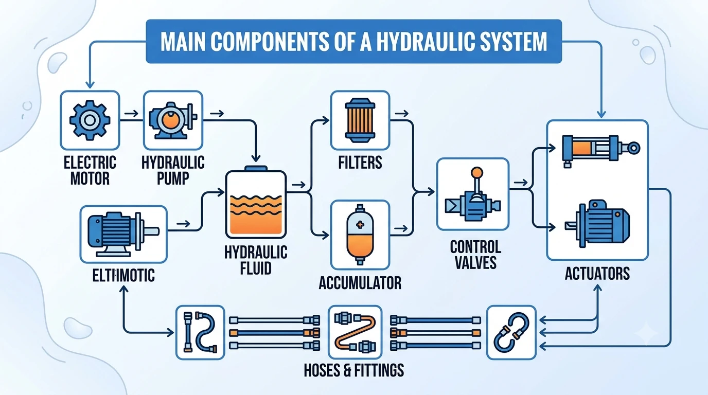
Main Components of a Hydraulic System
| Component | Main Function | Common Selection Factors |
|---|---|---|
Hydraulic pump |
Converts mechanical power into hydraulic flow |
Pressure, flow rate, displacement, efficiency |
Electric motor or engine |
Drives the pump |
Power rating, speed, duty cycle |
Reservoir |
Stores hydraulic oil |
Volume, cooling area, contamination control |
Hydraulic fluid |
Transmits power and lubricates parts |
Viscosity, temperature range, additives |
Control valves |
Control direction, pressure, and flow |
Valve type, flow capacity, response time |
Actuators |
Convert hydraulic energy into motion |
Load, speed, stroke, torque |
Filters |
Remove contamination from oil |
Micron rating, beta ratio, pressure drop |
Hoses and fittings |
Carry oil between components |
Pressure rating, bend radius, compatibility |
Accumulator |
Stores hydraulic energy |
Gas volume, pressure rating, safety requirements |
Cooler or heat exchanger |
Controls oil temperature |
Heat load, ambient temperature, flow rate |
Sensors and gauges |
Monitor system condition |
Pressure range, signal type, accuracy |
1. Hydraulic Pump

The hydraulic pump is the heart of the system. It does not directly create pressure; it creates flow. Pressure develops when the flow meets resistance from the actuator load, valve restrictions, or system design.
Common pump types include:
- Gear pumps: Simple, cost-effective, common in mobile and low-to-medium pressure systems.
- Vane pumps: Smooth flow, often used in industrial machines.
- Piston pumps: High efficiency and high-pressure capability, widely used in demanding industrial and mobile systems.
A poor pump selection can cause noise, heat generation, cavitation, and unstable actuator movement. For example, using a fixed displacement gear pump where variable flow is required may waste energy through the relief valve.
2. Reservoir
The reservoir stores hydraulic oil and supports cooling, deaeration, and contamination settling. A good reservoir design allows air bubbles to separate from oil before the fluid returns to the pump inlet.
Important reservoir features include:
- Sufficient oil volume
- Baffles to separate return and suction flow
- Breather filter
- Drain port
- Clean-out cover
- Level and temperature indicator
Undersized reservoirs often contribute to high oil temperature and poor air separation.
3. Hydraulic Fluid
Hydraulic oil is both a power transmission medium and a lubricant. It also helps with cooling, corrosion protection, and sealing.
Key fluid properties include:
- Viscosity grade
- Anti-wear additives
- Oxidation resistance
- Water separation ability
- Compatibility with seals
- Operating temperature range
Too high viscosity can cause poor cold-start performance and suction problems. Too low viscosity can increase internal leakage and reduce pump life.
4. Hydraulic Valves

| Valve Type | Function | Example |
|---|---|---|
Directional control valve |
Controls actuator directio |
4/3 spool valve |
Pressure control valve |
Limits or regulates pressure |
Relief valve, reducing valve |
Flow control valve |
Controls actuator speed |
Throttle valve, flow regulator |
5. Hydraulic Actuators
Actuators convert hydraulic power into mechanical work.
The two main types are:
- Hydraulic cylinders: Produce linear motion.
- Hydraulic motors: Produce rotary motion.
Cylinder selection depends on bore size, rod diameter, stroke length, mounting style, speed, load direction, and pressure rating. Hydraulic motor selection depends on torque, speed, displacement, efficiency, and case drain requirements.
6. Filters

Contamination is one of the most common causes of hydraulic component failure. Particles can damage pump surfaces, valve spools, seals, and actuator components.
Common filter locations include:
- Suction filter or strainer
- Pressure filter
- Return line filter
- Offline kidney-loop filter
- Breather filter
For high-performance hydraulic systems, filtration should be selected according to the sensitivity of the most critical component, often servo valves, proportional valves, or piston pumps.
7. Hoses, Tubes, and Fittings
Hydraulic hoses and fittings connect the system. They must be rated for working pressure, impulse cycles, temperature, fluid compatibility, and installation conditions.
Common issues include:
- Incorrect hose routing
- Tight bend radius
- Abrasion
- Over-tightened fittings
- Wrong seal type
- Pressure rating mismatch
Hydraulic hose failure can create serious safety hazards, especially in high-pressure systems.
8. Accumulator

An accumulator stores hydraulic energy using compressed gas, usually nitrogen. It can provide emergency power, absorb shock, reduce pulsation, or supplement pump flow during peak demand.
Common accumulator types include:
- Bladder accumulator
- Piston accumulator
- Diaphragm accumulator
Accumulators require careful safety handling because stored pressure remains even after the pump stops.
9. Cooler or Heat Exchanger
Hydraulic systems lose energy as heat through pumps, valves, throttling, and internal leakage. If oil temperature rises too high, viscosity drops, seals age faster, and component wear increases.
Common cooling methods include:
- Air-oil cooler
- Water-oil heat exchanger
- Reservoir surface cooling
A system that constantly overheats usually has an underlying problem: incorrect pump sizing, excessive relief valve flow, undersized lines, worn components, or poor heat exchanger capacity.
10. Sensors, Gauges, and Control Electronics
Modern hydraulic systems often include pressure sensors, temperature sensors, flow meters, level switches, proportional valve amplifiers, PLC control, and condition monitoring.
These components help detect:
- Pressure spikes
- Filter clogging
- Oil overheating
- Low oil level
- Abnormal actuator speed
- Pump performance decline
For predictive maintenance, pressure and temperature trends are often more useful than single readings.
How Hydraulic Components Work Together
A typical hydraulic circuit works like this:
- The electric motor drives the pump.
- The pump draws oil from the reservoir.
- Oil passes through filters and flows into the valve block.
- Directional valves route oil to the actuator.
- Pressure valves protect the system from overload.
- Flow valves control actuator speed.
- Return oil flows back through filters and cooling devices.
- The reservoir stores and conditions the oil for reuse.
Each component must be matched to the system’s required pressure, flow, duty cycle, environment, and safety requirements.
Selection Guide
| Requirement | Component Selection Focus |
|---|---|
High force |
Cylinder bore, system pressure, relief valve setting |
High speed |
Pump flow, valve capacity, hose size |
High precision |
Proportional valves, servo valves, feedback sensors |
Low cost |
Gear pump, simple valve stack, standard cylinders |
High efficiency |
Variable displacement pump, load-sensing circuit |
Harsh environment |
Sealed connectors, corrosion-resistant fittings, proper fluid |
Long service life |
Filtration, cooling, correct fluid viscosity, conservative ratings |
Common Problems and Troubleshooting
| Problem | Possible Cause | Practical Check |
|---|---|---|
Slow actuator |
Low pump flow, internal leakage, clogged filter |
Check flow rate and pressure drop |
System overheating |
Relief valve bypass, undersized cooler, worn pump |
Check oil temperature and return flow |
Noisy pump |
Cavitation, air ingress, low oil level |
Inspect suction line and reservoir level |
Cylinder drift |
Worn seals, leaking valve spool |
Isolate cylinder and check leakage |
Low pressure |
Relief valve setting, worn pump, external leak |
Test pressure at pump outlet |
Foaming oil |
Air ingress, wrong oil, poor reservoir design |
Check suction fittings and return line |
Frequent filter clogging |
Dirty oil, component wear, poor maintenance |
Perform oil analysis |
Maintenance Tips
- Check oil level and temperature regularly.
- Replace filters based on differential pressure, not only calendar time.
- Keep breathers clean and correctly rated.
- Inspect hoses for abrasion, cracking, and leakage.
- Verify relief valve settings during scheduled maintenance.
- Avoid mixing incompatible hydraulic fluids.
- Use proper flushing after component failure.
- Keep suction lines short, sealed, and unrestricted.
- Record pressure, temperature, and noise changes over time.
FAQs
Q1:What are the main components of a hydraulic system?
The main components of a hydraulic system are the hydraulic pump, reservoir, hydraulic fluid, control valves, actuators, filters, hoses, fittings, accumulator, cooler, and monitoring devices.
Q2:What is the most important component in a hydraulic system?
Q3:What component controls pressure in a hydraulic system?
Q4:What component controls speed in a hydraulic system?
Q5:Why do hydraulic systems fail?
Authority Sources
- ISO 4413:2010 hydraulic fluid power safety requirements
- National Fluid Power Association
- Parker Industrial Hydraulics technical literature
- Yuken Basic Hydraulics and Components