
Introduction
A hydraulic lift motor raises and lowers a load against gravity. You find one on a scissor lift, a boom platform, a vehicle hoist, or a dock leveler. The job sounds simple. The engineering is not.
Gravity never switches off. The load hangs the moment you stop feeding pressure. A lift motor has to raise the load, hold it at height, and lower it under control. Fail any of the three, and someone gets hurt.
This guide covers how a hydraulic lift motor works in real lift service. It walks through gravity dynamics and the safety valves that prevent drops. It covers brake integration and sizing for four lift types you see in the field.
What is a Hydraulic Lift Motor
A hydraulic lift motor is a rotary actuator that drives a lifting mechanism. Pressurized oil enters, turns the output shaft, and the shaft drives the lift. The mechanism may be a screw, a chain, a drum, or a pump.
Most lift motors fall into two groups. High-speed motors run a pump that feeds a lift cylinder. Low-speed high-torque motors turn a drum or screw directly. The lift type sets which one you need.
The word “lift” changes the engineering. A motor on a conveyor coast to a stop. A lift motor must hold the load the instant the flow stops. That holding requirement drives the valve and brake package.
How It Works
Oil enters the motor inlet at working pressure and pushes the internal working parts. Gears, vanes, or pistons convert that push into shaft torque. The shaft couples to the lift mechanism and raises the load.
Three numbers set the output. Displacement in cc per rev fixes torque per bar. Pressure in bars fixes how hard the shaft twists. Flow in liters per minute fixes how fast the load rises. Change one, and the lift behaves differently.
The motor raises the load when the directional valve feeds the inlet. To hold, you close the valve and trap oil. To lower, you meter flow out of the motor. The motor responds to what the circuit feeds it. The safety hardware does the holding.
Lift Dynamics: Gravity, Holding, and Lowering
Gravity makes a lift different from every other drive. The load pushes down all the time. Three torque values define the job.
Breakaway torque overcomes static friction and starts the lift. It runs 1.2 to 2 times the running torque. Running torque holds the load rising at a steady speed. Holding torque keeps the load at height with zero flow. Lowering the torque meters the load under control.
Inertia matters on the way up. The load plus the mechanism has mass. Acceleration torque equals mass times acceleration divided by time squared. Size the motor for breakaway and acceleration. Then check it against holding and lowering.
Types of Lift Motors by Application
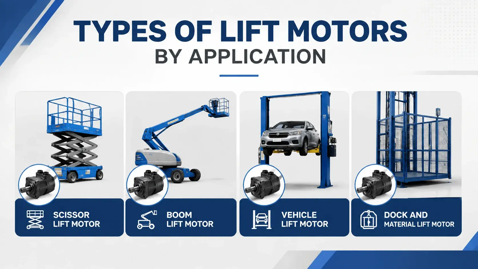
Four lift jobs cover most of what these motors do. Each one sizes differently and fails differently.
Scissor Lift Motor
A scissor lift raises a platform on linked arms. The load stays level and rises straight up. A high-speed motor drives a pump that feeds the lift cylinder. Pressure runs 150 to 250 bar. Breakaway torque sets the size. A check valve holds the platform.
Boom Lift Motor
A boom lift swings a platform on an articulated arm. The load swings, tilts, and reaches. A low-speed high-torque motor drives the lift cylinder pump or a drum. Overspeed on the down-swing kills booms. An overcenter valve holds and meters. Pressure runs 200 to 350 bar.
Vehicle Lift Motor
A vehicle lift raises a car or truck for service. The load sits still and rises straight. A high-speed motor runs a pump that feeds two or four cylinders. Holding comes from a mechanical lock or a pilot check. Pressure runs 150 to 300 bar. Duty runs light.
Dock and Material Lift Motor
A dock lift or material lift moves freight between levels. The load varies and shocks on entry. A motor-pump group feeds the lift cylinder. A flow control valve sets the lower speed. Pressure runs 100 to 210 bar. Survival depends on the relief valve.
Lift Type Comparison
| Lift Type | Motor Type | Pressure (bar) | Key Safety Valve | Main Failure |
|---|---|---|---|---|
Scissor |
High-speed and pump |
150 to 250 |
Check valve |
Breakaway stall |
Boom |
LSHT |
200 to 350 |
Overcenter |
Overspeed on down-swing |
Vehicle |
High-speed and pump |
150 to 300 |
Pilot check and lock |
Drift at height |
Dock and material |
Motor-pump group |
100 to 210 |
Relief and flow control |
Shock on entry |
Safety Valves and Brake Integration
A bare hydraulic lift motor will not hold a load safely. The safety hardware does the holding.
Counterbalance valves trap oil in the motor and hold the load. They open the metered flow when the inlet pressure drops below the load pressure. This prevents runaway on the way down. Every gravity-load lift needs one.
Overcenter valves do the same job and add control in both directions. They suit boom lifts and any lift the load can drive. A pilot check valve locks the load mechanically. It holds even if a hose bursts.
Brake release ports tie the brake to motor pressure. The brake releases only when the motor produces torque. When the flow stops, the brake clamps. A motor with a spring-applied brake holds the load even at zero pressure.
Sizing and Selection
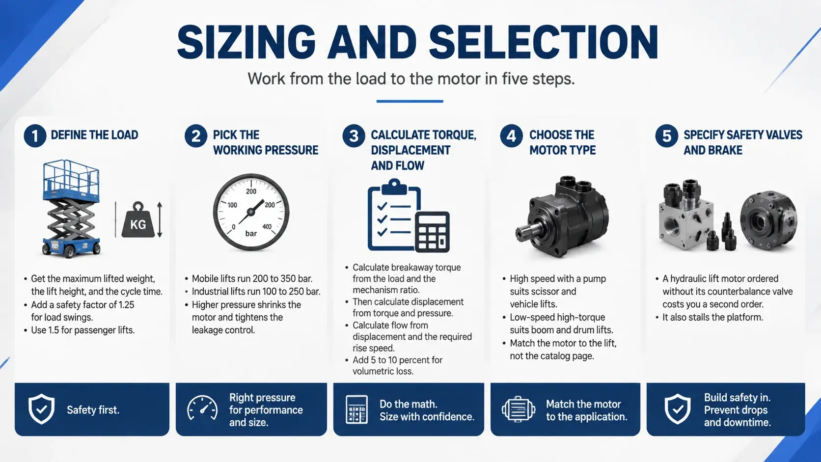
Work from the load to the motor in five steps.
Define the load. Get the maximum lifted weight, the lift height, and the cycle time. Add a safety factor of 1.25 for load swings. Use 1.5 for passenger lifts.
Pick the working pressure. Mobile lifts run 200 to 350 bar. Industrial lifts run 100 to 250 bar. Higher pressure shrinks the motor and tightens the leakage control.
Calculate the breakaway torque from the load and the mechanism ratio. Then calculate displacement from torque and pressure. Calculate the flow from displacement and the required rise speed. Add 5 to 10 percent for volumetric loss.
Choose the motor type. High speed with a pump suits scissor and vehicle lifts. Low-speed high-torque suits boom and drum lifts. Match the motor to the lift, not the catalog page.
Specify the safety valves and brake on the same sheet. A hydraulic lift motor ordered without its counterbalance valve costs you a second order. It also stalls the platform.
Common Lift Motor Failures
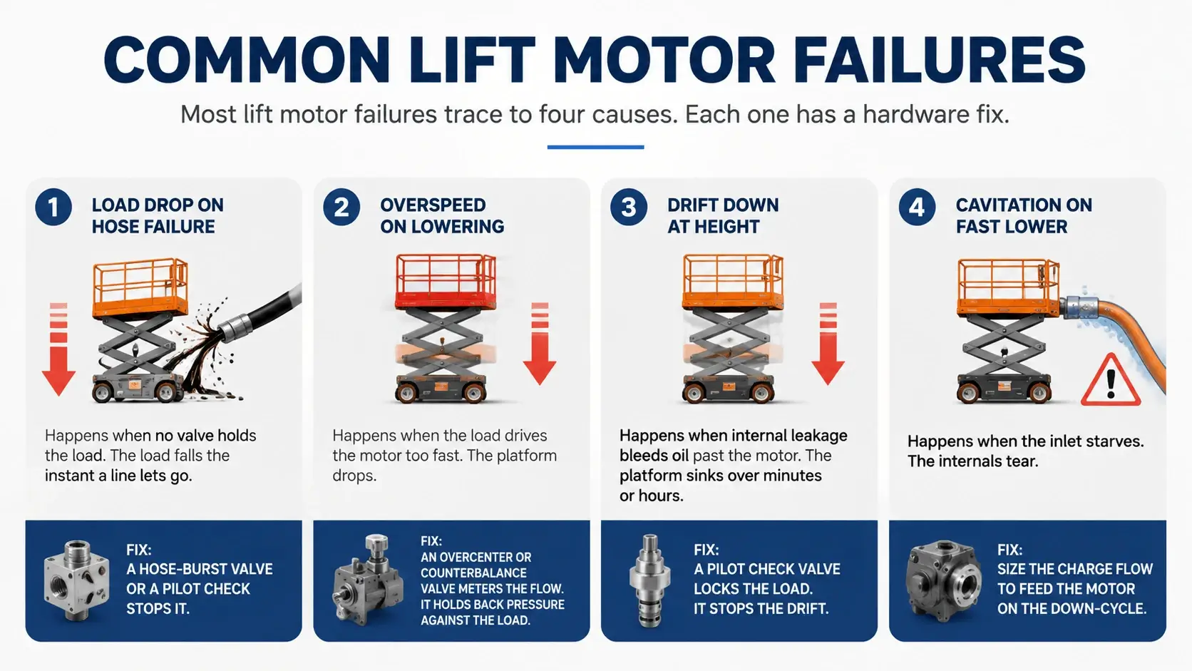
Most lift motor failures trace to four causes. Each one has a hardware fix.
A load drop on hose failure happens when no valve holds the load. The load falls the instant a line lets go. A hose-burst valve or a pilot check stops it.
Overspeed on lowering happens when the load drives the motor too fast. The platform drops. An overcenter or counterbalance valve meters the flow. It holds back pressure against the load.
Drift down at height happens when internal leakage bleeds oil past the motor. The platform sinks over minutes or hours. A pilot check valve locks the load. It stops the drift.
Cavitation on the fast lower happens when the inlet starves. The internals tear. Size the charge flow to feed the motor on the down-cycle.
Maintenance for Lift Service
Fluid health decides lift motor life. Sample every 500 hours for particle count, viscosity, and water. Hold ISO 4406 to 20/18/15 for general lifts. Use 18/16/13 for high-pressure piston lifts.
Trend the holding drift. Raise the platform to full height and shut down. Measure the sink for over ten minutes. A rising drift means internal wear is eating the seals or the valve seat.
Check the safety valves at every service. A counterbalance that drifts its setting lets the load creep. A pilot check that leaks lets the platform sink. Both fail slowly until they fail fast.
Inspect the brake and its release pressure. A brake that drags burns energy and heats the oil. A brake that releases late chatters against the load. Set the sequence so the brake opens just before torque builds.
FAQ
What is a hydraulic lift motor?
It is a rotary actuator that drives a lifting mechanism against gravity. Pressurized oil turns the shaft. The shaft raises a platform, a boom, or a vehicle.
How does a hydraulic lift motor hold the load?
The motor does not hold the load. A counterbalance, an overcenter, or a pilot check traps oil in the circuit. A spring-applied brake clamps the shaft when the flow stops.
What safety valves does a lift motor need?
A counterbalance or overcenter valve prevents runaway lowering. A pilot check locks the load against hose failure. A cross-port relief absorbs shock. A hose-burst valve protects passenger lifts.
How do you size a hydraulic lift motor?
Start with breakaway torque, not running torque. Add a safety factor. Pick the pressure. Calculate displacement and flow. Match the motor type to the lift mechanism.
Why does a lift platform drift down at height?
Internal leakage in the motor, valve, or cylinder bleeds oil past the sealing surfaces. The load sinks. A pilot check valve locks the load and stops the drift.
What causes a lift to drop when lowering?
Overspeed. The load drives the motor faster than the circuit meters the outlet flow. A counterbalance or overcenter valve holds back pressure. It meters the flow to a safe speed.
Conclusion
The motor works where fluid power meets gravity. The motor raises the load. The safety valves and the brake hold it. Get the lift dynamics right. Match the valve package and brake to the load. The platform then runs for thousands of cycles. Get them wrong, and no motor survives the first overloaded descent.