
Introduction
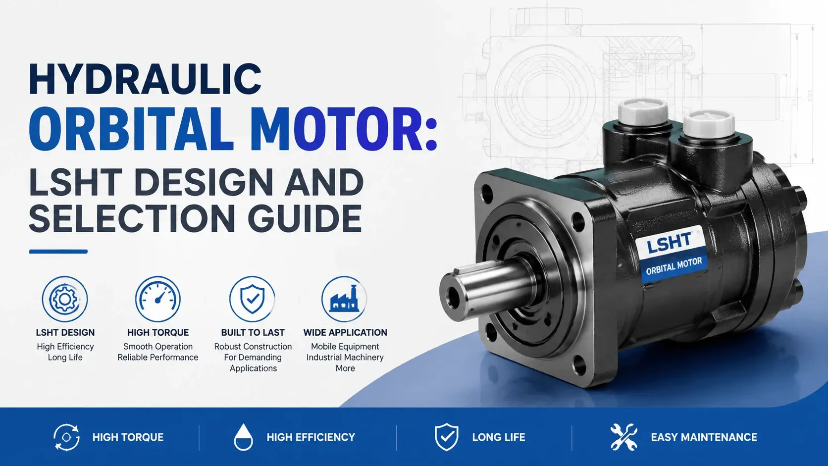
A hydraulic orbital motor turns fluid power into slow, heavy rotation. You find one on an auger gearbox, a street sweeper brush, a fertilizer reel, or a conveyor head shaft. The motor sits where you need high torque at low speed, without a gearbox eating the space.
The orbiting rotor inside gives the motor its name and its character. A six-tooth star rotor rolls inside a seven-chamber stator ring, and each chamber expands and contracts as the rotor orbits. That geometry packs a lot of displacement into a small housing. The result is a torque that a gear or vane motor of the same frame size cannot match.
This guide covers how the orbital motor works, what separates gerotor from geroler, how the valve porting changes efficiency, and how to size one for real service. The goal is a motor that matches the load and survives the cycle.
What is a Hydraulic Orbital Motor
A hydraulic orbital motor is a low-speed, high-torque rotary actuator built around an orbiting internal gear set. Pressurized oil enters the valve, routes into the stator chambers, and pushes the star rotor into an orbiting roll. The rotor couples through a driveshaft to the output, and the shaft delivers torque to the load.
The orbit matters. The rotor does not spin on its own center. It rolls around the inside of the stator, and the driveshaft picks up that motion through a cardanic coupling or a splined interface. One full orbit of the rotor produces several shaft revolutions, which gives the motor its high torque multiplication.
Displacement ranges from roughly 50 to 1500 cc per revolution across the family. Speeds run 5 to 800 rpm, depending on frame size. Continuous pressure lands between 70 and 250 bar, with peak ratings up to 320 bar on heavy-duty units. The package stays compact because the geometry does the work.
How an Orbital Motor Works
Oil enters the motor through the port plate and passes into the valve. The valve tracks the rotor position and routes pressurized oil into the chamber behind each rotor tooth in sequence. As one chamber fills and pushes, the opposite chamber drains spent oil to the return port.
The rotor has one fewer tooth than the stator has chambers. A six-tooth rotor runs inside a seven-chamber stator. As the rotor orbits, each tooth sweeps past each stator chamber in turn. The chamber volume grows on the pressurized side and shrinks on the drain side, and the pressure difference rolls the rotor forward.
One complete orbit of the rotor around the stator center equals six tooth engagements, and the output shaft turns six times for each orbit on a six-to-seven set. That ratio sets the displacement per revolution of the output shaft. Change the tooth count, the rotor size, or the chamber depth, and you change the torque and speed of the motor.
Gerotor Versus Geroler
Two geometries carry the orbital motor family, and the difference is a row of rollers.
Gerotor
A gerotor uses a solid star rotor running in direct metal contact with the stator ring. The tooth tips slide along the stator wall under load. Friction eats a few percent of efficiency, and the contact wears over time. Gerotor units cost less and suit moderate-duty service where price drives the decision.
Geroler
A geroler puts rollers into the stator chambers between the rotor teeth and the ring wall. The rotor teeth roll over the rollers instead of sliding on bare metal. Rolling contact drops the friction, raises the mechanical efficiency, and improves the starting torque. You pay for it in part count and price.
| Feature | Gerotor | Geroler |
|---|---|---|
Contact type |
Sliding metal |
Rolling on rollers |
Mechanical efficiency |
85 to 90 percent |
90 to 95 percent |
Starting torque efficiency |
70 to 80 percent |
80 to 90 percent |
Wear rate |
Higher |
Lower |
Cost |
Lower |
Higher |
Typical service |
Light to moderate duty |
Heavy and continuous duty |
The roller motor costs more and runs longer. For an auger that turns eight hours a day, the geroler pays back in seal life and efficiency. For a sweeper brush that runs intermittently, a gerotor does the job for less money.
Valve Porting: Spool and Disc
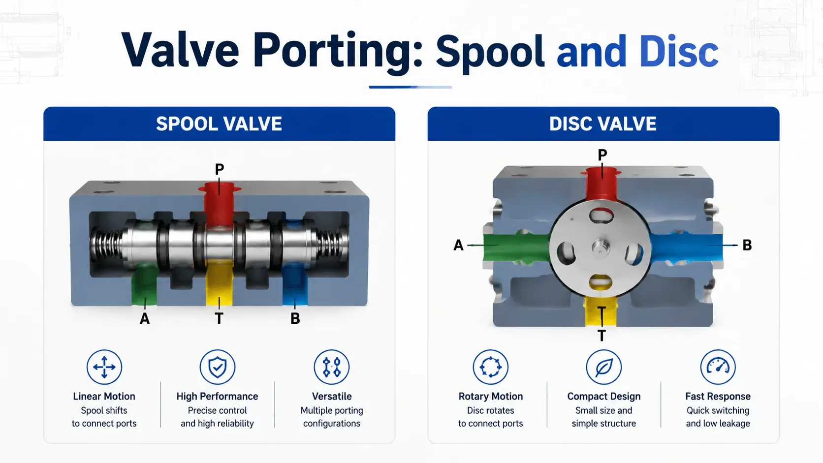
The valve tracks the rotor position and routes oil to the right chambers. Two valve types do this job, and each changes how the motor behaves.
Spool Valve
A spool valve uses a cylindrical spool driven off the rotor through a coupling pin or a dowel. The spool slides and rotates to align its metering grooves with the chamber ports. Spool valves are simple and cheap. They have clearance leakage that drops efficiency a few points, and they wear into a sluggish response over time.
Disc Valve
A disc valve uses a flat rotating disc that seals against the port face. The disc tracks the rotor and opens the chambers in sequence. Disc valves seal tighter than spool valves, so the volumetric efficiency runs higher and the starting response feels crisper. The trade is a part that costs more and needs a clean fluid supply to survive.
Most buyers pick the valve by the application. Intermittent duty tolerates a spool valve. Continuous or positioning service rewards a disc valve with better efficiency and less drift.
Performance Characteristics
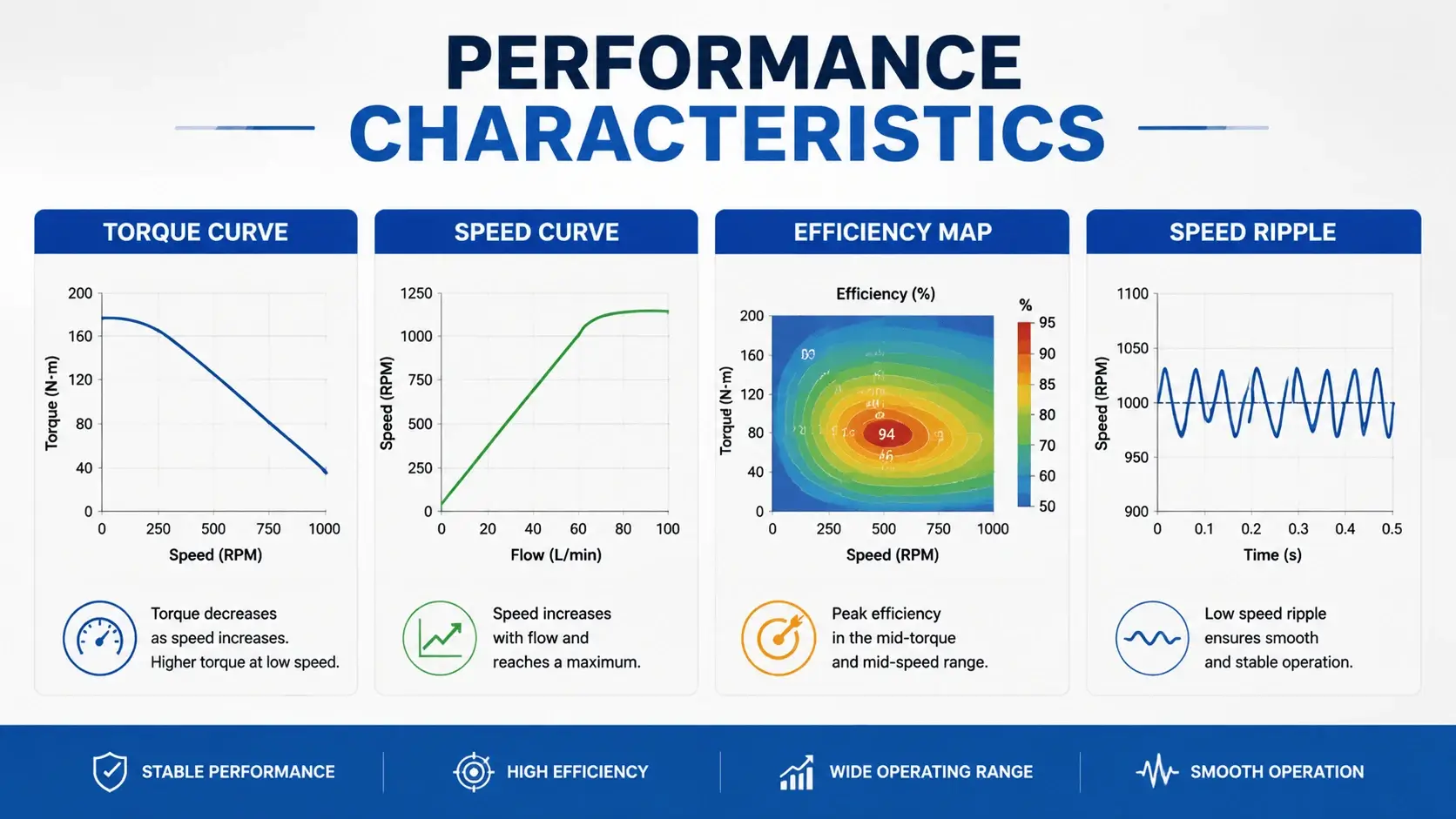
Three curves define a hydraulic orbital motor, and you need all three before you order.
Torque Curve
The torque curve shows output torque against pressure. Torque scales linearly with pressure and displacement up to the relief limit. A 100 cc per rev motor at 100 bar produces roughly 16 Nm. Double the pressure and you double the torque, until the housing or the bearing hits its structural cap.
Speed Curve
The speed curve shows output speed against flow. Speed equals flow divided by displacement, minus volumetric leakage. A 100 cc per rev motor at 20 L/min turns close to 200 rpm at zero load and drops to 170 or 180 rpm at full pressure as leakage steals flow.
Efficiency Map
The efficiency map shows where the motor earns its keep. Volumetric efficiency runs 90 to 97 percent at rated speed and drops at the low-speed end as leakage takes a bigger share. Mechanical efficiency runs 85 to 95 percent and peaks in the mid-speed band. Overall efficiency lands between 75 and 90 percent across the working range, with the geroler and disc valve combinations at the top.
Speed Ripple
Speed ripple sets the orbital motor apart from piston motors. The chamber-to-chamber transition produces a small torque pulsation at the output. You see it as a speed wobble at low rpm. For a conveyor it is fine. For a positioning drive it needs a cushion or a different motor family.
Advantages of Orbital Motors
The hydraulic orbital motor earns its place on four strengths.
High Torque Density
The orbiting geometry packs displacement into a housing the size of a coffee can. A 500 cc per rev orbital motor fits where a 500 cc piston motor would not, and it delivers the torque at a shaft speed the application actually wants.
Low Cost Per Newton-Meter
The gerotor construction uses fewer parts than a piston motor. The housing, the rotor set, the valve, and the shaft make up the bill of materials. That simplicity keeps the price down and the lead time short.
Good Starting Torque
A geroler motor holds 80 to 90 percent of its running torque at zero speed. That matters for augers and reels that start under load. A piston motor needs a higher pressure margin to do the same job from rest.
Compact Package With Integrated Valve
The valve mounts inside the motor housing. You get a directional control and a motor in one block, and the plumbing stays short. On mobile equipment the space and weight savings add up fast.
Limitations and Trade-offs
No motor fits every job, and the orbital family has real limits.
Speed Ceiling
Orbital motors top out between 500 and 800 rpm on most frames. The orbiting rotor sets a mechanical speed limit, and the valve porting chokes the flow above it. High-speed service needs a gear or axial piston motor.
Efficiency Band
The motor runs at 75 to 90 percent overall, which trails a good piston motor by 5 to 10 points. On a continuous-duty drive that gap shows up as heat and fuel cost. The orbital motor earns its keep on torque density and price, not on peak efficiency.
Speed Ripple and Noise
The chamber transition produces a torque pulsation that you hear as a gear whine and see as a low-speed wobble. Sensitive positioning drives do not like it. A piston motor runs smoother.
Bearing Side Load
The output shaft carries the rotor side thrust on some designs. A heavy radial load from a chain or pulley shortens the bearing life. Check the allowable radial load on the datasheet before you hang a drive off the shaft.
Industrial Applications
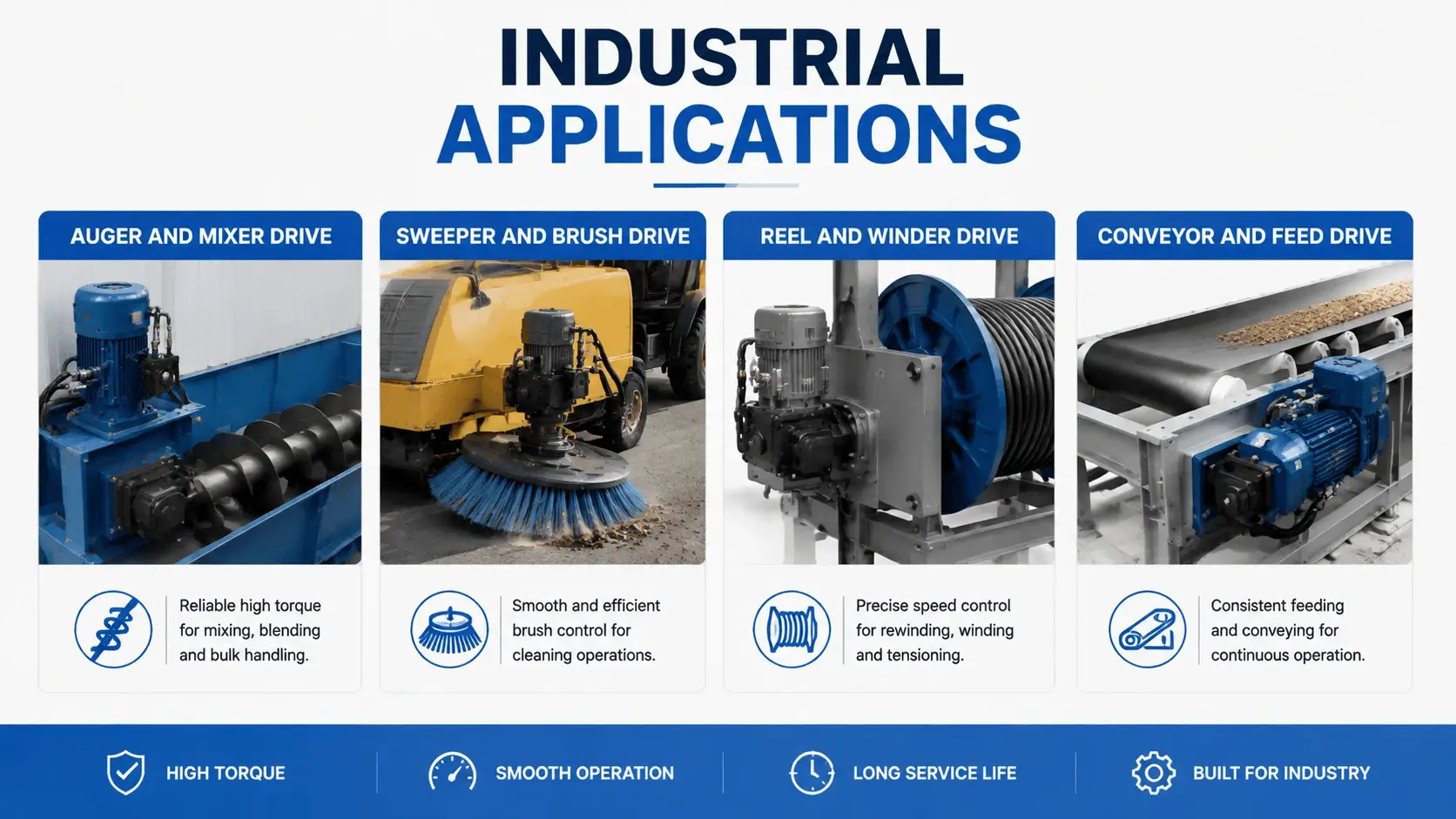
Four load types cover most of what these motors do well.
Auger and Mixer Drive
An auger drive turns a grain, feed, or cement screw. The load starts under rest torque and runs at a steady low speed. Starting torque efficiency decides if the auger starts or stalls. Orbital motors run 50 to 400 cc per rev at 100 to 200 bar and 50 to 300 rpm. A geroler with a disc valve fits this duty well.
Sweeper and Brush Drive
A sweeper brush turns at 150 to 400 rpm and sees intermittent shock from debris. The motor runs a light duty cycle, and cost matters more than peak efficiency. A gerotor with a spool valve fits this service. Run a cross-port relief so a jammed brush does not burst the line.
Reel and Winder Drive
A fertilizer or hose reel pulls a steady load and needs holding torque at low speed. The motor runs 100 to 500 cc per rev and holds 100 to 210 bar. A geroler gives the starting torque and the low-speed smoothness the reel wants. Add a counterbalance valve so the reel does not overrun on the payout.
Conveyor and Feed Drive
A conveyor head shaft moves material at a steady speed and sees peak torque when a jam loads the belt. The motor runs 80 to 250 cc per rev at 100 to 210 bar. A gerotor or geroler both work here. Size for breakaway torque from the jam, not the running load, and put a relief valve in the circuit.
Selection and Sizing Guide
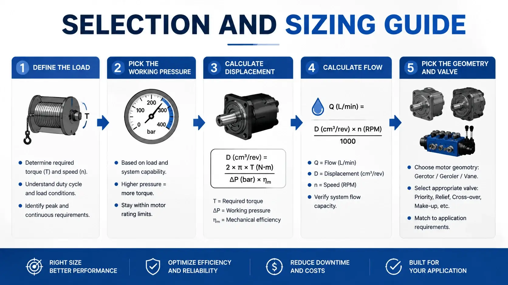
Work from the load to the motor in five steps.
Define the Load
Get the breakaway torque, the running torque, the peak torque, and the speed range. Note the duty cycle. A conveyor that runs 20 percent of the time sizes differently than an auger that runs continuous.
Pick the Working Pressure
Mobile equipment runs 100 to 210 bar. Agricultural implements run 70 to 160 bar on the lower-cost open-center circuits. Industrial drives run 160 to 250 bar. Higher pressure shrinks the motor and tightens the leakage control.
Calculate Displacement
Torque equals pressure times displacement divided by 62.8, with torque in Nm, pressure in bar, and displacement in cc per rev. Solve for displacement from your breakaway torque and working pressure. Add 10 percent for mechanical and volumetric loss.
Calculate Flow
Flow equals displacement times speed, divided by 1000, with flow in L/min and speed in rpm. Add 5 to 10 percent for leakage. Check the result against the pump and the line size.
Pick the Geometry and Valve
Continuous duty and high starting torque means a geroler with a disc valve. Intermittent duty and low cost means a gerotor with a spool valve. Specify the mounting flange, the shaft type, and the ports on the same sheet.
Common Failures and Prevention
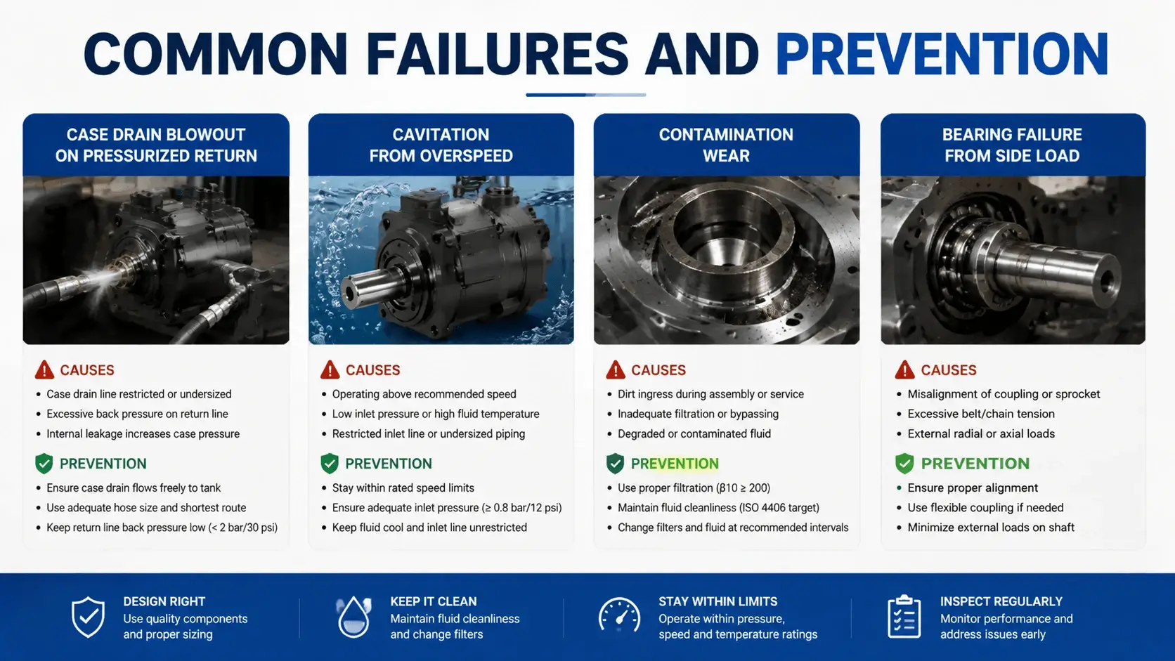
Four failure modes eat orbital motors in the field.
Case Drain Blowout on Pressurized Return
The shaft seal sees tank pressure. If the return line runs through a restriction or a shared backpressure, the seal pops and the oil pours out. Run the case drain straight to tank above the oil level. Never tee it into a pressurized return.
Cavitation From Overspeed
A load that drives the motor faster than the pump feeds it starves the inlet and tears the rotor. A charge check or a meter-in flow control stops it. Listen for a gravel sound on the overrunning part of the cycle.
Contamination Wear
Hard particles score the rotor teeth and the valve track. The motor loses displacement and gains leakage. Hold the fluid to ISO 4406 20/18/15 for standard duty and 19/17/14 for geroler service. Sample the oil every 500 hours.
Bearing Failure From Side Load
A chain, pulley, or sprocket on the output shaft applies a radial load the bearing was not sized for. The bearing brinells and the shaft walks. Use a motor with a larger bearing, or move the side load to an external pillow block.
FAQ
What is a hydraulic orbital motor?
A hydraulic orbital motor is a low-speed high-torque actuator built around a star rotor that orbits inside a stator ring. The orbiting motion produces high displacement and high torque in a compact housing.
What is the difference between gerotor and geroler?
A gerotor runs the rotor in direct sliding contact with the stator wall. A geroler puts rollers between the rotor teeth and the stator. The rollers drop the friction, raise the efficiency, and improve the starting torque at a higher cost.
How does an orbital motor produce torque?
Pressurized oil fills the chamber behind each rotor tooth in sequence. The pressure difference across the rotor rolls it around the stator. The driveshaft picks up the motion and delivers torque to the load.
What pressure can an orbital motor run?
Most orbital motors run 70 to 250 bar continuous with peak ratings to 320 bar. Agricultural and mobile units run the lower end. Heavy-duty geroler units run the top end.
How do you size an orbital motor?
Start with breakaway torque and working pressure. Calculate displacement from torque equals pressure times displacement divided by 62.8. Then calculate flow from displacement times speed. Pick gerotor or geroler from the duty cycle and the starting torque need.
What causes orbital motor failure?
Four causes lead. Pressurized return lines blow the shaft seal. Overspeed on overrunning loads cavitates the rotor. Contamination wears the rotor and valve. Side load on the output shaft kills the bearing. Each failure is preventable with correct plumbing, fluid care, and load management.
Conclusion
A hydraulic orbital motor wins where you need high torque at low speed in a small package. The orbiting rotor geometry packs displacement that no gear or vane motor of the same size can match, and the geroler roller design raises the starting torque and the efficiency where the application demands it. Get the geometry, the valve, and the sizing right, and the motor runs for thousands of hours. Get the plumbing or the side load wrong, and no orbital motor survives the duty cycle.