
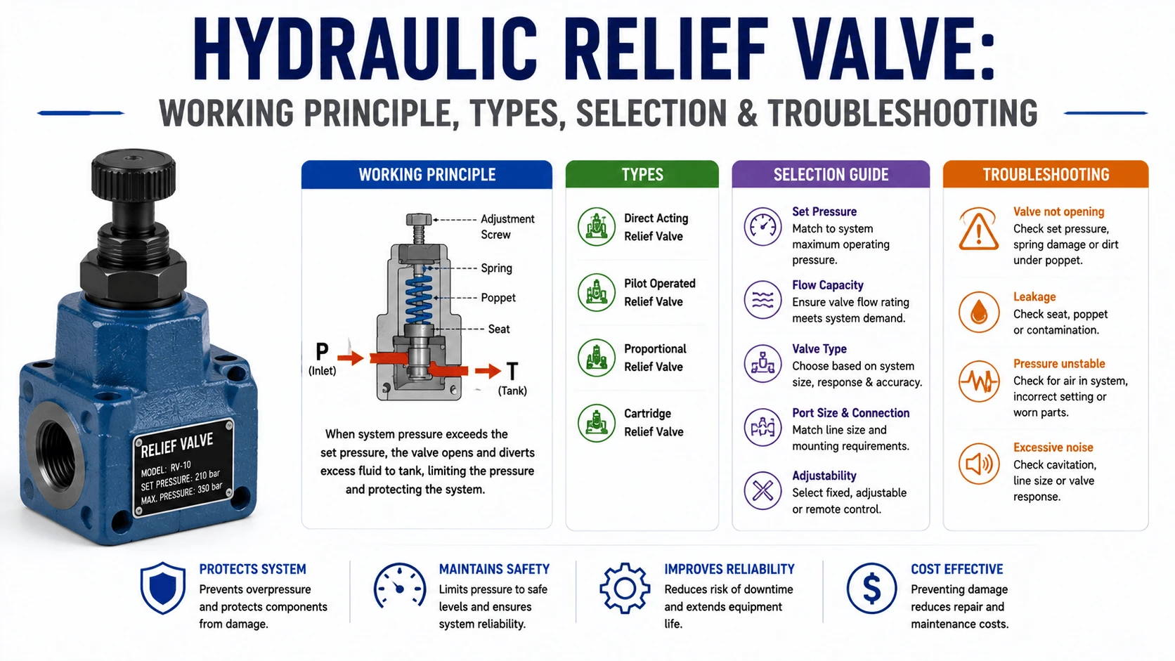
What is a Hydraulic Relief Valve?
How it Works
Main Types of Hydraulic Relief Valves
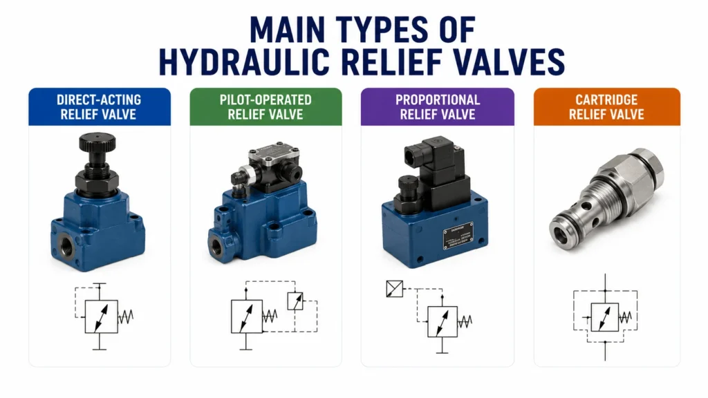
| Type | Best For | Advantages | Limitations |
|---|---|---|---|
Direct-acting relief valve |
Low-flow circuits, compact manifolds, fast response |
Simple, rugged, quick opening |
More pressure override at higher flow |
Pilot-operated relief valve |
Main system pressure control, high-flow circuits |
Better pressure stability, lower override |
More complex, sensitive to contamination |
Proportional relief valve |
Electronically controlled pressure systems |
Adjustable pressure by signal |
Requires electronics and clean oil |
Cartridge relief valve |
Manifold blocks, mobile hydraulics |
Compact, easy to integrate |
Requires correct cavity and flow path |
Direct-Acting vs Pilot-Operated Relief Valve
Main Components
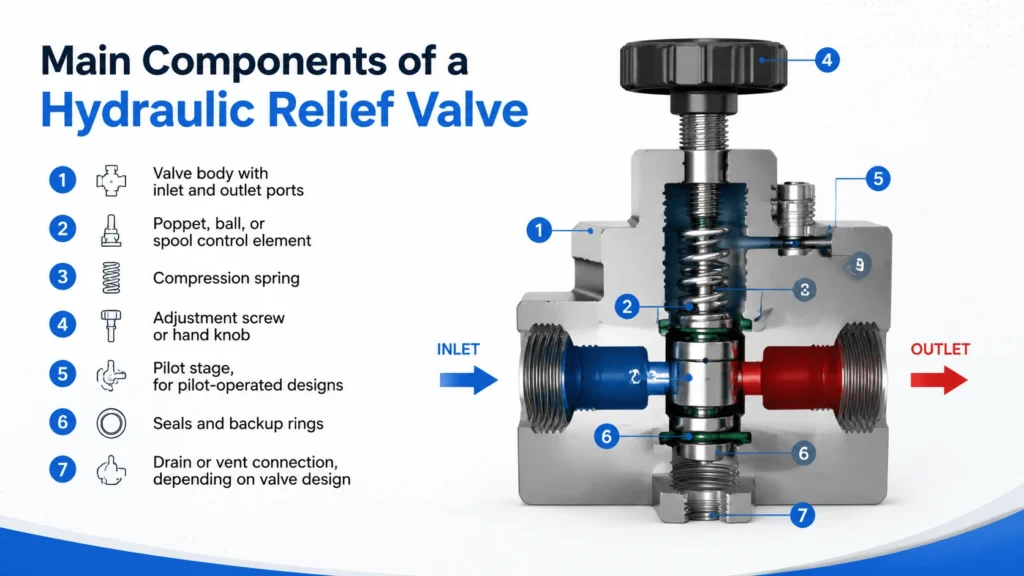
A hydraulic relief valve normally includes:
- Valve body with inlet and outlet ports
- Poppet, ball, or spool control element
- Compression spring
- Adjustment screw or hand knob
- Pilot stage, for pilot-operated designs
- Seals and backup rings
- Drain or vent connection, depending on valve design
The internal geometry affects response, leakage, noise, and pressure stability. Two valves with the same nominal pressure rating may behave differently if one has better flow characteristics or lower pressure override.
Advantages
Hydraulic relief valves provide several engineering benefits:
- Protect pumps, actuators, hoses, and manifolds from overpressure
- Limit the maximum force in cylinders and hydraulic presses
- Reduce the risk of hose burst or component cracking
- Help control pressure spikes during load changes
- Provide a simple mechanical safety layer independent of electronics
Disadvantages
Relief valves also have limitations:
- Continuous relief flow wastes energy and generates heat
- Incorrect settings can reduce machine force or damage components
- Contamination can cause leakage, sticking, or unstable pressure
- Oversized or poorly selected valves may chatter
- A relief valve should not be used as a normal flow-control device
If oil is constantly passing over the relief valve during normal operation, the circuit should be reviewed. In many systems, that indicates poor unloading strategy, incorrect pump selection, or a valve setting conflict.
Industrial Applications
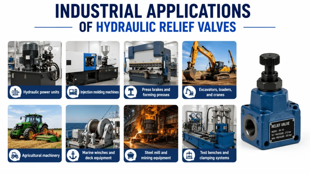
Hydraulic relief valves are used in:
- Hydraulic power units
- Injection molding machines
- Press brakes and forming presses
- Excavators, loaders, and cranes
- Agricultural machinery
- Marine winches and deck equipment
- Steel mill and mining equipment
- Test benches and clamping systems
In a hydraulic press, the relief valve limits the maximum pressing force. In mobile equipment, it protects the pump and actuator circuits when a cylinder reaches end stroke or a load exceeds the design limit.
Common Problems and Failure Modes
| Symptom | Likely Cause | Engineering Note |
|---|---|---|
System cannot reach pressure |
Relief valve set too low, worn seat, broken spring |
Check pressure with a calibrated gauge |
Pressure spikes above setting |
Valve undersized, slow response, blocked return line |
Review flow capacity and tank line restriction |
Valve chatters or vibrates |
Air in oil, unstable flow, wrong valve size, contamination |
Check suction leaks and oil condition |
Excessive oil temperature |
Relief valve flowing continuously |
Measure return-line temperature and pump load |
Pressure drifts after adjustment |
Spring fatigue, contamination, pilot leakage |
Inspect valve internals and filtration |
External leakage |
Damaged seals or loose fittings |
Confirm seal material matches fluid and temperature |
Troubleshooting Guide
- Verify the pressure reading. Use a calibrated pressure gauge installed at the correct test point. A gauge installed far from the valve may miss local pressure spikes or line losses.
- Check the relief setting. Back off the adjustment, then increase pressure gradually under controlled conditions. Do not exceed the rated pressure of the lowest-rated component in the circuit.
- Inspect oil cleanliness. Pilot-operated valves are especially sensitive to contamination. Dirty oil can hold a poppet slightly open or block a pilot orifice.
- Check return-line restriction. A relief valve discharging to a restricted tank line may not control pressure correctly. Return flow should have a low-pressure path to tank.
- Confirm valve sizing. The valve must pass the maximum pump flow at an acceptable pressure rise. Do not size only by port thread.
- Look for continuous bypass flow. If the relief valve is hot while the machine is idle, oil may be flowing across the valve continuously. That is an energy loss and heat source.
Selection Guide
When selecting a hydraulic relief valve, confirm these specifications:
| Selection Factor | What to Check |
|---|---|
Pressure range |
Set pressure should fall comfortably within the valve’s adjustment range |
Maximum flow |
Valve must handle full pump flow without excessive pressure override |
Valve type |
Direct-acting for simple/low-flow; pilot-operated for stable high-flow systems |
Port or cavity |
Match CETOP/ISO mounting, threaded ports, or cartridge cavity |
Fluid compatibility |
Mineral oil, water-glycol, biodegradable oil, or fire-resistant fluids |
Temperature range |
Seal and body materials must match working temperature |
Leakage allowance |
Important for load-holding and energy-sensitive circuits |
Adjustment method |
Screw, handwheel, tamper-resistant cap, or proportional control |
Certification needs |
Safety-related circuits may require documented testing or approved valves |
A common procurement mistake is replacing a failed relief valve only by thread size and pressure range. Flow rating, pressure override curve, mounting interface, and pilot/drain configuration are equally important.
Maintenance Tips
- Keep hydraulic oil within the recommended ISO cleanliness level for the valve type.
- Replace filters based on differential pressure indicators, not only calendar intervals.
- Check relief pressure during scheduled service, especially on presses and lifting equipment.
- Do not adjust the valve to compensate for a weak pump without diagnosis.
- Inspect for abnormal heat near the relief valve body.
- Use the correct torque when installing cartridge valves.
- Replace damaged seals with compatible materials such as NBR, FKM, or EPDM depending on fluid type.
- Record the final pressure setting after adjustment.
FAQ
What does a hydraulic relief valve do?
A hydraulic relief valve limits maximum system pressure by opening at a preset pressure and diverting hydraulic oil to the tank or a low-pressure return path.
Where should a hydraulic relief valve be installed?
It is commonly installed near the pump outlet or in the main pressure manifold. Additional relief valves may be installed in actuator circuits to protect specific loads.
What is the difference between direct-acting and pilot-operated relief valves?
A direct-acting valve uses system pressure directly against a spring-loaded element. A pilot-operated valve uses a smaller pilot stage to control a larger main valve, giving better pressure stability in high-flow systems.
Why is my hydraulic relief valve getting hot?
Heat usually indicates that oil is flowing across the relief valve for too long. This may be caused by an incorrect pressure setting, blocked actuator, valve malfunction, or poor unloading circuit design.
Can a relief valve be used to control normal working pressure?
It can limit maximum pressure, but it should not be used as the primary method for continuous pressure control. Continuous relief flow wastes energy and increases oil temperature.
How do I size a hydraulic relief valve?
Size it by maximum system pressure, full pump flow, pressure override curve, port or cavity type, fluid compatibility, and temperature range. Port size alone is not enough.
Authority Sources
- ISO 4413:2010 overview — hydraulic fluid power safety requirements for systems and components.
- NFPA fluid power standards — standards purchasing and reference hub.
- Parker pressure relief valves — manufacturer reference for relief valve function and product categories.
- Bosch Rexroth pilot-operated pressure relief valve data — example of industrial pilot-operated relief valve specifications.
- ANSI/NFPA pressure relief valve testing preview — performance data and testing reference.
Need help selecting a hydraulic relief valve for your machine or power unit? Contact our engineering team with your pressure range, pump flow, fluid type, port size, and application details. We can help match the correct direct-acting, pilot-operated, or cartridge relief valve for reliable system protection.