
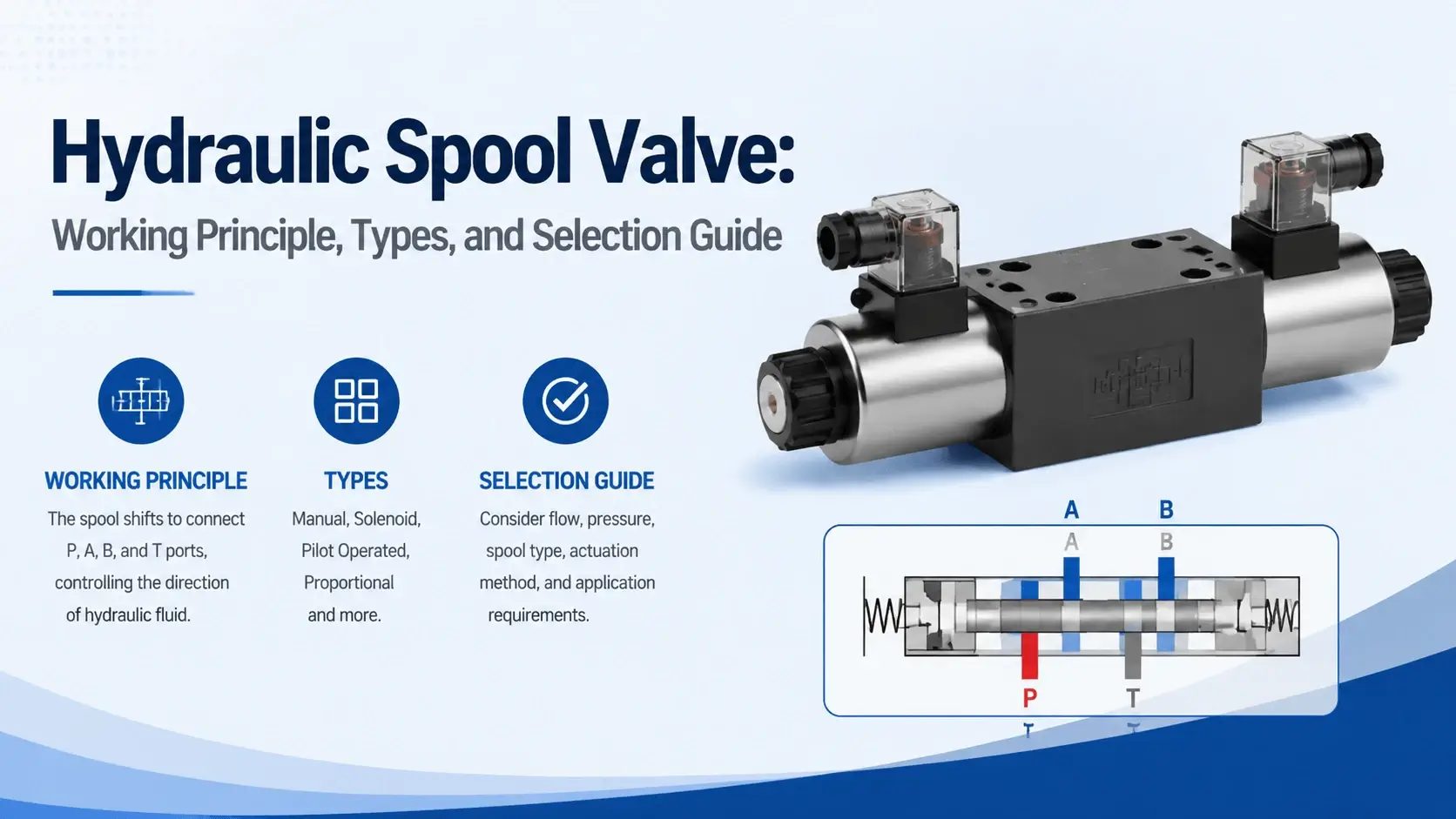
If you have worked with directional control valves, you have handled a hydraulic spool valve, whether you called it that or not. The sliding spool is the workhorse inside most 4/3 and 4/2 directional valves used on excavators, press machines, injection molding equipment, and material handling systems. Understanding how it works, what goes wrong, and how to pick the right one saves time during design and money during operation.
What is a Hydraulic Spool Valve
A hydraulic spool valve is a directional control device that uses a cylindrical spool sliding axially inside a precision-machined valve body bore to connect or block fluid passages. Move the spool in one direction, and the flow goes from port P to port A while port B returns to the tank. Shift it the opposite way, and the paths reverse. The center position determines what happens when no one actuates the valve.
Why Spool Valves Dominate
The concept dates back decades. It remains dominant because spool valves handle high flows, withstand repeated cycling, and cost less than poppet-style alternatives for most applications above 50 L/min. You will find them wherever a machine needs to route oil between a pump, an actuator, and a tank.
How the Sliding Spool Works
Basic Sliding Mechanism
The spool itself looks like a metal rod with wider sections called lands and narrower grooves between them. The lands seal against the valve body bore to block flow. The grooves align with body ports to permit flow. When a solenoid, pilot pressure, or lever shifts the spool, different ports connect or disconnect.
Position and Flow Patterns
Think of it as a rotating selector switch but linear instead of rotary. Each spool position corresponds to a distinct flow pattern. A standard 4/3 valve has left, center, and right positions. Some specialized valves add additional positions for sequencing or regeneration circuits.
Flow Forces on the Shifting Spool
Pressure at the inlet acts on the spool lands. This creates axial flow forces that oppose the shifting motion. At 350 bar with 100 L/min flow, those forces can reach 30-80 N depending on land diameter and flow path geometry. Pilot-operated designs overcome this by applying pressure on a larger area end. Direct solenoid valves rely on stronger coils or wet-armature designs.
Spool Anatomy: Lands, Grooves, Undercuts, and Notches
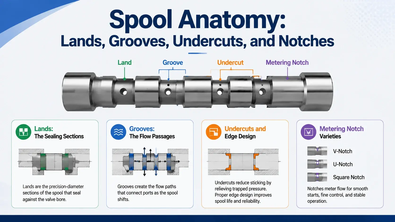
Every spool valve has specific features that determine its performance profile.
Lands: The Sealing Sections
Lands are the raised, diametrical sections that close off ports. Typical land width ranges from 4 mm to 12 mm, depending on valve size and pressure rating. Wider lands give better sealing but increase spool length and shift travel.
Grooves: The Flow Passages
Grooves are the recessed areas between lands. When a groove lines up with a port in the body, oil flows through. Groove depth affects flow capacity. Deeper grooves mean more flow area but also more internal volume that compresses during transients.
Undercuts and Edge Design
Undercuts (also called chamfers or notches on the land edges) control how flow opens and closes as the spool moves past a port edge. A square-edge land gives abrupt on-off behavior. An undercut or notched land provides gradual metering, which reduces pressure spikes and shock.
Metering Notch Varieties
Metering notches come in several shapes. Triangular notches give a progressive flow area increase. V-notches with varying angles offer different gain curves. Circular undercuts are simpler to manufacture but provide less predictable metering. Some high-performance valves use proprietary notch profiles optimized for specific applications like boom control or excavator attachment circuits.
Lap Conditions: Open Center, Closed Center, and Zero Lap
The relationship between spool land width and port width in the body defines the lap condition. This single design choice affects system efficiency, heat generation, and controllability more than any other spool parameter.
Closed-Center (Positive Lap)
Closed-center (positive lap) means the spool land is wider than the body port. A dead zone exists where all ports are blocked during transition. This gives positive load holding but causes a step change in flow when the spool breaks over. Pressure builds until the land clears the port edge, then flow jumps. Operators feel this as a jerky start. Closed-center spools work well for holding circuits where drift is unacceptable.
Open-Center (Negative Lap)
Open-center (negative lap) means the land is narrower than the port. All ports connect briefly during spool transition. No dead zone, so control feels smooth from the first millimeter of stroke. The downside is continuous internal leakage even at neutral. Open-center systems run warmer and consume more power at idle. Many mobile machines use open-center pumps matched with open-center valves for simplicity.
Zero-Lap (Critical Center)
Zero-lap (critical center) attempts to eliminate both dead zone and crossover leakage. Manufacturing tolerance makes true zero-lap nearly impossible. Most valves sold as zero-lap actually have 1-2% of land width as either positive or negative. Servo-class valves get closest with ground spools and lapped bodies, but temperature changes still shift the effective lap by several microns.
Lap Condition Comparison
| Lap Type | Neutral Leakage | Dead Zone | Shock | Best Application |
|---|---|---|---|---|
Closed |
Very low |
Yes |
Moderate |
Load holding, clamping |
Open |
High |
None |
Low |
Mobile equipment, smooth control |
Zero |
Minimal |
Minimal |
Low |
Servo systems, precision motion |
Matching Lap to Application
Choosing the wrong lap condition explains half the field complaints about jerky cylinders or hot tanks. Match the spool to the circuit, not just the flow rating.
Flow Forces on the Spool
Two types of flow forces act on a hydraulic spool valve spool. Both matter for sizing actuators and predicting response.
Steady-State Flow Force
Steady-state flow force (sometimes called Bernoulli force) results from momentum change as fluid accelerates through the restriction between land and body port. The high-velocity jet exerts a force that always tries to push the spool toward the closed position. For a typical 6 mm land diameter at 250 bar with 60 L/min flow, steady-state force runs 15-40 N depending on the flow passage shape. Wider flow windows reduce velocity and thus reduce this force.
Transient Flow Force
Transient flow force occurs only while the spool is moving. As the opening changes, the fluid mass inside the chamber accelerates or decelerates. This creates a force proportional to the rate of change of flow area times the pressure drop. During fast spool shifts, transient forces can exceed steady-state forces briefly. In extreme cases they cause spool oscillation or chatter.
Force Compensation Methods
Compensation methods include using pressure compensation slots, shaping the spool lands to balance momentum flux, or adding damping orifices in pilot lines. Most standard valves accept the force penalty and oversize the solenoid or pilot piston accordingly. High-response servo valves almost always incorporate some form of flow force compensation.
Metering Notch Design and Control Quality
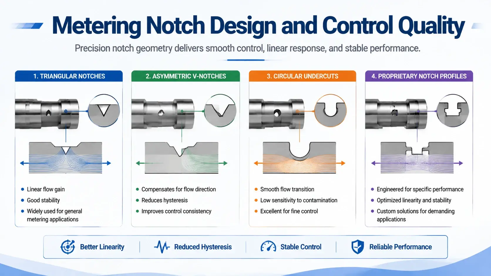
The shape of metering notches on the spool lands directly affects how smoothly a cylinder or motor starts, stops, and changes speed. A poorly chosen notch profile causes either sluggish response or aggressive jerkiness that operators hate and that damages mechanical components.
Triangular Notches
Triangular notches with 30-60 degree included angle give a roughly progressive area curve. Flow increases slowly at first then faster as the spool opens further. This matches many operator preferences because fine positioning happens near center where small spool movements produce small flow changes.
Asymmetric V-Notches
V-notches with asymmetric sides allow different characteristics in each direction. One side might open quickly for fast extend, the other slowly for controlled retract. Excavator boom valves often use this approach.
Circular Undercuts
Circular undercuts machined into the land edges are the cheapest option. Area versus stroke follows a sine-like curve. Not ideal for precise metering but acceptable for simple on-off applications where shock is managed by accumulators or cross-over relief valves.
Proprietary Notch Profiles
Some manufacturers use proprietary notch geometries. Rexroth calls theirs “metering edge design.” Parker uses “notched spool technology.” Danfoss optimizes per application family. The details vary but the goal remains the same: match the flow-gain curve to what the machine needs.
Leakage Paths and Why They Matter
No hydraulic spool valve seals perfectly. Clearance between the spool outer diameter and the valve body bore allows oil to leak from high-pressure ports to low-pressure ports. This internal leakage wastes power, generates heat, and can cause unwanted actuator drift.
Radial Clearance Standards
Radial clearance typically runs 5-20 microns depending on valve size and manufacturing class. A standard CETOP 3/NG6 directional valve might have 8-12 micron clearance. Servo valves hold 2-5 microns. Larger clearances reduce the risk of binding from contamination but increase leakage.
The Leakage Formula
Leakage flow follows the orifice equation approximately. For laminar flow in the annular gap, leakage Q_leak equals (π * D * h^3 * ΔP) / (12 * μ * L), where D equals spool diameter, h equals radial clearance, ΔP equals pressure difference, μ equals dynamic viscosity, and L equals land length. The cubic dependence on clearance means doubling the gap from 10 to 20 microns increases leakage eightfold. This is why worn spools with scored bodies cause such dramatic efficiency loss.
Real-World Leakage Numbers
At 210 bar differential across a land, a valve with 10 micron clearance and 10 mm land length running ISO VG 46 oil at 50°C leaks roughly 0.1-0.3 L/min per land. A 4/3 valve has multiple lands so total neutral leakage can reach 1-2 L/min. That sounds small but adds up to 200-400 watts of continuous heat generation. Over an eight-hour shift, that is several kWh wasted.
External Shaft Seal Leakage
External leakage past the spool shaft seals is another concern. Rod seals wear and eventually weep. Catch this early during inspection before it becomes a housekeeping problem and an environmental issue.
Common Failure Modes
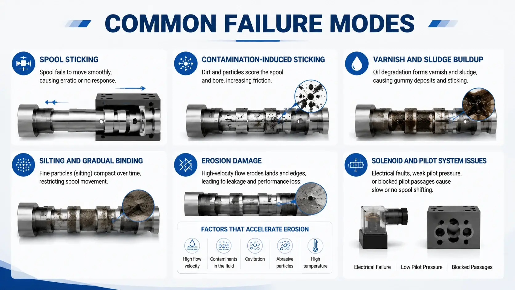
Spool Sticking
Sticking is the number one complaint with any hydraulic spool valve. The spool binds and will not shift, or shifts sluggishly with high force requirement.
Contamination-Induced Sticking
Contamination causes most sticking incidents. Particles larger than the radial clearance jam between the spool and bore. A 15 micron particle in a 10 micron gap locks the spool solid. This is why filtration at the valve inlet matters. ISO 4406 cleanliness code 17/15/12 or better is recommended for most directional valves operating above 210 bar.
Varnish and Sludge Buildup
Varnish and sludge from oxidized oil also cause sticking. Thermal cycling deposits residue on the spool surface. Over months, the buildup thickens enough to increase friction. Oil analysis detects oxidation early. Changing oil before total acid number exceeds 0.3 mg KOH/g prevents most varnish problems.
Silting and Gradual Binding
Silting describes a subtler form of sticking where fine particles accumulate in the clearance gap around the spool lands. Radial clamping force from pressure unbalance pushes the spool against the bore wall. Particles collect in the resulting crescent-shaped gap on the low-pressure side. The spool still moves but requires a higher force. Operators report the valve feels stiff.
Erosion Damage
High-velocity jets from partially open ports erode the spool lands and body areas over time. The erosion pattern looks like grooves or washouts near the metering edges. Once erosion starts, the flow pattern changes locally, which accelerates further damage. Severely eroded spools show increased leakage, altered flow characteristics, and sometimes an inability to hold pressure.
Factors That Accelerate Erosion
Operating pressures above 350 bar or water-based fluids (lower lubricity, higher density) accelerate erosion. Hardened spool materials help. Some manufacturers apply tungsten carbide coating or chrome plating to critical surfaces.
Solenoid and Pilot System Issues
Not every spool problem originates in the spool itself. Burnt solenoid coils, degraded pilot pressure, stuck pilot valves, or electrical connection faults all prevent proper spool shifting. Always check the actuation system before condemning the spool. I have seen technicians replace perfect spools because the real fault was a loose crimp terminal on the solenoid lead.
Selection Criteria
Picking the right spool valve means matching several parameters to your application simultaneously.
Flow Rate Sizing
Flow rate determines valve size. A valve too small causes excessive pressure drop. A valve too high costs more and may give poor low-flow controllability. Size for peak flow plus 20% margin. Check the manufacturer’s pressure-drop curve at your maximum flow. Keep total valve pressure drop below 25-35 bar at rated flow for efficient operation.
Pressure Rating Margin
Pressure rating must exceed your system working pressure with a margin. If your system runs at 250 bar, specify a 315 or 350 bar valve. Shock spikes from sudden load changes can momentarily double working pressure. Most industrial valves handle this if the nominal rating has adequate headroom.
Lap Condition Selection
Lap condition, as discussed earlier, should match the circuit function. Holding circuits need a closed center. Smooth motion control benefits from open or zero lap. When in doubt, ask the valve supplier for a recommendation based on similar installed applications.
Actuation Method Choice
Actuation method matters for response speed and force availability. Direct solenoid valves work up to about 35 L/min and 250 bar, depending on size. Beyond that, pilot-operated valves use system pressure or an external pilot supply to shift the spool. Proportional valves with position feedback give the best control but cost significantly more.
Environmental Considerations
Environmental factors include temperature range, vibration exposure, and contamination level. Outdoor mobile applications face -20°C to +60°C ambient. Cold starts increase oil viscosity, which raises the shift force. Hot environments thin the oil and increase leakage. High vibration loosens connectors and can cause fretting corrosion on electrical contacts.
Mounting Configuration
Mounting configuration follows ISO 4401 (CETOP) standards for most industrial valves. ISO 4401-03 (CETOP 3 / NG6), ISO 4401-05 (CETOP 5 / NG10), ISO 4401-07 (CETOP 7 / NG16), and ISO 4401-08 (CETOP 8 / NG25) cover the common sizes. Subplate mounting allows valve replacement without disturbing line plumbing. Threaded port valves suit compact manifolds and tight spaces.
Maintenance and Troubleshooting
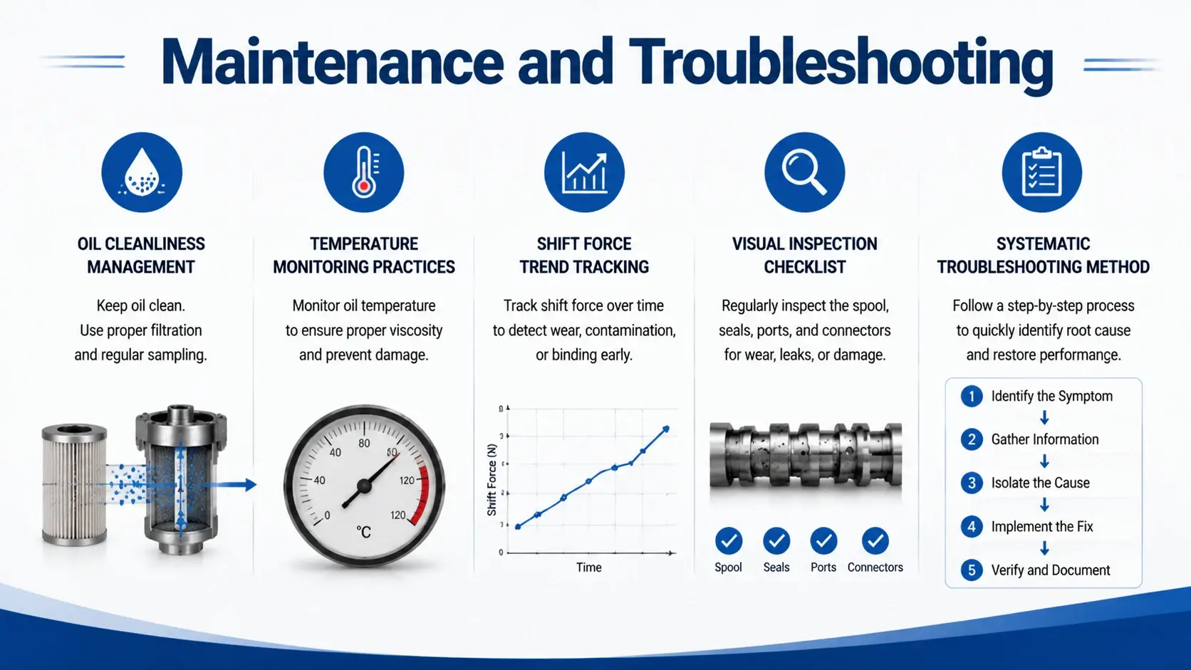
Preventive maintenance extends hydraulic spool valve service life dramatically compared to run-to-failure approaches.
Oil Cleanliness Management
Oil cleanliness is non-negotiable. Install and maintain filters rated for the target cleanliness level. Check filter differential indicators weekly. Change elements when indicated, not on a calendar schedule alone. Sample oil quarterly and send to a lab for particle count, viscosity, and oxidation analysis.
Temperature Monitoring Practices
Temperature monitoring catches problems early. A valve running 10°C hotter than surrounding system temperature suggests excessive leakage or partial blockage. Use infrared thermography during routine inspections. Compare identical valves on the same machine. Any outlier deserves investigation.
Shift Force Trend Tracking
Shift force monitoring reveals developing friction issues. If pilot pressure required to shift a valve creeps upward over weeks, something is dragging. Log the readings. Trend data predicts failures before complete seizure occurs.
Visual Inspection Checklist
Visual inspection during planned downtime should include checking solenoid terminals for corrosion, inspecting manual override mechanisms for freedom of movement, and looking for external leaks around shaft seals and body joints. Pull a spool occasionally for direct examination if the valve history suggests risk.
Systematic Troubleshooting Method
When troubleshooting a suspected valve problem, isolate the variable. Swap the suspect valve with a known-good valve on the same machine. If the fault moves, the valve was bad. If the fault stays, look elsewhere in the circuit. This simple swap test saves hours of diagnostic time.
FAQ
What is the difference between a spool valve and a poppet valve?
A spool valve slides axially to open and close flow paths. A poppet valve lifts a cone or ball off a seat. Spool valves handle higher flows with lower shift force but leak internally. Poppet valves seal tightly with zero leakage but require more force to open against pressure and typically handle lower flows. Choose spool for general directional control. Choose poppet when zero-leakage load holding is mandatory.
How do I know if my spool valve is open center or closed center?
Check the valve model number against the manufacturer’s catalog. The spool symbol on the nameplate shows center position flow paths. Blocked ports mean closed center. Connected ports (usually P to T) mean open center. If the tag is missing, test with the system pressurized at neutral. Measure flow from P to T at the tank line. Significant flow indicates open center. Near-zero flow indicates closed or tandem center.
What causes a spool valve to whistle or squeal?
Cavitation from localized low pressure near metering edges usually causes noise. High velocity through small openings drops pressure below oil vapor pressure. Bubbles form and collapse violently, producing the characteristic whine. Reduce system inlet restriction, lower operating speed, or select a valve with larger flow capacity or gentler metering notches. Air entrainment in the oil causes a different sound, more like grinding or rattling.
Can I repair a spool valve or must I replace it?
Light scoring on the spool can sometimes be removed by careful lapping with fine abrasive paste. Deep scores, erosion washouts, or warped spools warrant replacement. Valve bodies with damaged bores are usually uneconomical to repair unless the valve is very large or specialized. Rebuild kits including spool, springs, and seals are available for most major brands. Compare kit cost plus labor against new valve price. For smaller valves (NG6, NG10), replacement often makes economic sense.
How often should I replace the spool valve in my system?
There is no fixed interval. A well-maintained valve in clean oil at moderate pressures lasts 10,000 to 20,000 operating hours or longer. Harsh conditions with contamination, high pressure cycling, or temperature extremes cut that life substantially. Base replacement decisions on condition monitoring data rather than calendar time. Track shift pressure trends, leakage measurements, and oil analysis results.
Conclusion
The hydraulic spool valve seems simple, a sliding cylinder inside a bore. But the engineering behind land geometry, lap condition, flow force management, and notch profiling separates a valve that works reliably from one that causes constant problems. Most field failures trace back to contamination, incorrect selection for the application, or neglected maintenance rather than manufacturing defects.
Get the basics right. Specify the correct lap condition for your circuit. Size adequately for flow and pressure. Maintain oil cleanliness below ISO 4406 18/16/13. Monitor shift force and temperature trends. When problems arise, diagnose systematically before replacing parts.
If you are designing a new system or troubleshooting an existing one and want application-specific guidance on spool valve selection, contact our engineering team. We stock CETOP 3 through CETOP 8 directional valves in open, closed, and zero-lap configurations from leading manufacturers, and our application engineers can review your circuit diagram to recommend the optimal configuration.