
Introduction
What is a Throttle Valve?
How a Throttle Valve Works
The Orifice Equation
Why Flow Drifts With Load
Throttle Valve vs Needle Valve vs Flow Control Valve
Types of Throttle Valves
Simple Throttle Valve
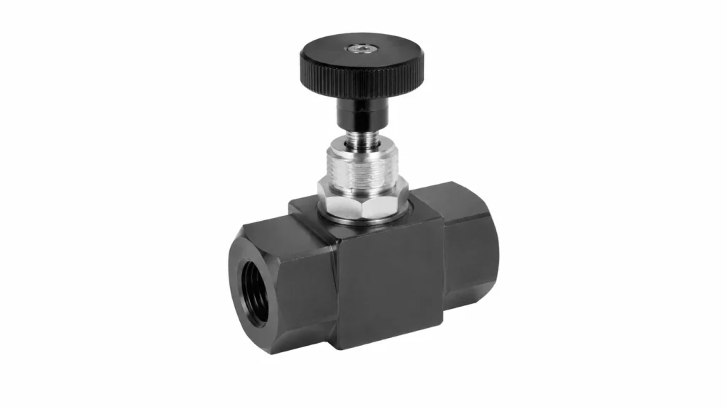
Throttle Check Valve (One-Way Throttle)

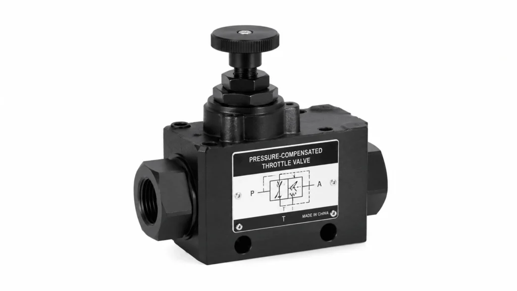
Pressure-Compensated Throttle Valve
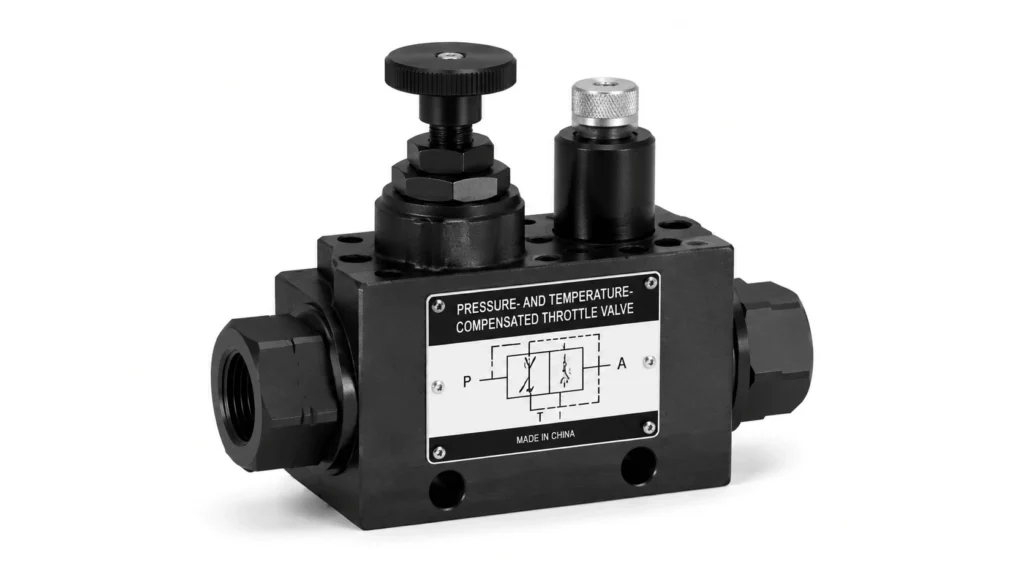
Pressure-and-Temperature-Compensated Throttle Valve
Throttle Valve Comparison Table
| Type | Flow vs Load ΔP | Reverse Flow | Typical Use | Relative Cost |
|---|---|---|---|---|
Simple throttle |
Drifts with load |
Throttled both ways |
Steady loads, flow balancing |
Low |
Throttle check valve |
Drifts with load |
Free reverse, throttled forward |
Cylinder retract control |
Low to medium |
Pressure-compensated throttle |
Held constant |
Throttled both ways |
Variable loads, stable speed |
Medium to high |
P&T-compensated throttle |
Held constant |
Throttled both ways |
Long-run machine tools |
High |
Needle valve |
Drifts with load |
Throttled both ways |
Fine low-flow metering |
Low |
Flow-Control Circuits: Meter-In, Meter-Out, Bleed-Off
Where you place the throttle in the circuit changes everything about how the system behaves. There are three basic arrangements.
Meter-in puts the throttle on the inlet side of the actuator, controlling flow into the cylinder or motor. It suits resistive loads that always push against the motion, like lifting or pressing. It does not work for overrunning loads, where the load helps the motion. With meter-in and an overrunning load, the cylinder can outrun the oil supply, cavitate, and lurch.
Meter-out puts the throttle on the return side, controlling flow out of the actuator. Back pressure builds against the load, so meter-out handles both resistive and overrunning loads safely. This is why meter-out is the default choice on most mobile and industrial circuits. The cost is extra back pressure and more heat, because the oil dumps the throttling energy as heat on its way to the tank.
Bleed-off routes a portion of the pump flow back to the tank through the throttle, leaving the rest to drive the actuator. It is less precise than meter-in or meter-out because the actuator sees full pump pressure, and the throttle only bleeds excess. It is also more efficient, because you restrict only the bypassed flow, not the full flow to the actuator. Bleed-off suits cases where efficiency beats precision.
Key Specifications and What They Mean
The flow range tells you the adjustable band the valve can deliver at a stated ΔP. Always check the ΔP that the manufacturer used to rate it. A 40 L/min valve at 10 bar ΔP is not a 40 L/min valve at 3 bar.
Pressure rating is the maximum operating pressure. Industrial throttle valves commonly run to 210 or 350 bar, and cartridge versions reach 420 bar. Pick a rating with a margin above your relief valve setting.
Port size and standard matter for drop-in replacement. Look for ISO 6149 metric ports, SAE J1926 straight-thread ports, or CETOP mounting patterns. Mixing standards forces adapters that add restrictions and leak paths.
Adjustment style ranges from a plain hand knob to a tamper-proof set screw to a micrometer dial with a locking nut. Tamper-proof or lockable styles suit production machines where operators should not change the settings.
Cleanliness target is rarely on the datasheet, but matters a lot. A sharp-edged throttle erodes fast in dirty oil. Plan for ISO 4406 cleanliness of 18/16/13 or better for fine throttling.
Sizing a Throttle Valve
Sizing means matching the orifice area to your target flow at the real operating ΔP. Start with the orifice equation, rearranged to solve for area:
A = Q / (Cd × √(2 × ΔP / ρ))
Plug in your target flow Q, the discharge coefficient Cd (use 0.65 as a first guess), the expected ΔP, and the oil density (about 870 kg/m³ for ISO VG 46). The result is the orifice area you need.
Then pick a valve whose adjustable area range comfortably covers that value. A good rule is to operate the throttle in the middle 30 to 70% of its adjustment range. Run a valve wide open, and you lose resolution and any margin for wear. Run it nearly closed, and a tiny bit of contamination chokes the flow completely.
For pressure-compensated valves, the sizing question shifts. You size the rated flow at the compensator’s reference ΔP, usually 5 to 10 bar. Then confirm the system can supply that ΔP plus the load pressure. Undersizing a compensated valve starves the actuator; oversizing pushes you to the bottom of the range where the compensator gets twitchy.
Common Problems and Troubleshooting
Speed drift under changing load is the classic symptom of a non-compensated throttle doing exactly what it was designed to do. If the load varies and you need a stable speed, switch to a pressure-compensated flow control valve. No amount of adjustment fixes a physics problem.
Erratic or chattering flow usually means cavitation or air entrainment. Check for a clogged suction filter, low reservoir level, or air leaks on the inlet side. A throttle valve with too small an orifice at too high a ΔP can also cavitate. Opening the throttle slightly or moving to a larger valve often cures it.
Overheating oil is the energy you throw away at the restriction, showing up as heat. Meter-out and bleed-off circuits dump throttling energy continuously. If the reservoir cannot dissipate it, add a cooler or rethink the circuit. A pressure-compensated valve does not eliminate the loss, but it lets you run a smaller, more efficient ΔP.
Setting drift over time points at a loosened locknut or a worn throttling edge. Contaminated oil rounds off the sharp edge, the discharge coefficient rises, and the same handle position now passes more flow. Tighten the locknut, check the oil cleanliness, and inspect the throttling edge for erosion.
Sluggish response after a cold start is viscosity at work. Cold, thick oil passes less flow at the same ΔP. A temperature-compensated valve fixes it. On a plain throttle, expect the speed to climb as the oil warms up and plan the cycle around it.
Selection Guide
Start with the load. If the load is steady and speed drift is acceptable, a simple throttle or throttle check valve keeps cost and complexity down. If the load varies and speed must hold, go straight to a pressure-compensated flow control valve.
Next, decide the circuit. Meter-out is the safe default because it handles both resistive and overrunning loads. Use meter-in only for pure resistive loads where back pressure is unwanted. Use bleed-off when efficiency matters more than precise speed.
Then pick the variant. Need controlled retract but free extend? Choose a throttle check valve. Running long shifts with cold-to-hot oil swings? Pick a pressure-and-temperature-compensated unit. Doing fine metering at low flow? A needle valve gives the resolution you need.
Finally, confirm the ports, the pressure rating, and the adjustment style match the machine. A valve that is right on flow but wrong on ports costs you adapters and reliability.
Maintenance Tips
- Keep the oil clean. Target ISO 4406 18/16/13 or better for fine throttling. The throttling edge is the first part to suffer in dirty oil.
- Check the locknut on every scheduled service. A loose locknut lets the setting walk, and the operator blames the load.
- Inspect the throttling edge during rebuilds. A rounded or notched edge changes the discharge coefficient and the flow characteristic.
- Watch the oil temperature. Continuous meter-out throttling can push reservoir temperature past 60°C. Above that, viscosity drops, leakage rises, and oil life falls.
- Replace, do not regrind, a worn throttling element. Hand-grinding changes the edge geometry and the flow curve in ways you cannot predict.
Conclusion
A throttle valve is the simplest speed-control tool in hydraulics, and that simplicity is both its strength and its trap. It restricts flow cheaply and flexibly, but it does not compensate for load changes, and the energy it removes shows up as heat. The best engineers treat the orifice equation, the circuit choice, and the load type as one decision. Pick the circuit that matches the load. Size the orifice to the real ΔP. Reach for compensation the moment speed stability becomes a requirement. Do that, and the throttle valve becomes a reliable part of the design rather than a source of field callbacks.