

Introduction
Hydraulic valves are the decision-makers of a hydraulic system. Every change in cylinder direction, every regulated pressure limit, and every controlled actuator speed is the direct result of a valve opening, closing, or throttling at the right moment. Selecting the wrong valve type—whether a 4/3 directional valve where a 3/2 would suffice, or a simple needle valve where a pressure-compensated flow control is required—leads to sluggish response, energy waste, premature wear, and unplanned downtime.
This guide is written for engineers, maintenance teams, and procurement professionals who need a complete, technically accurate map of hydraulic valve types. Rather than stopping at the usual “three categories” overview, it covers pressure ratings, actuation methods, international mounting standards, failure modes, and a structured selection process you can apply directly to a circuit design or replacement decision.
What is a Hydraulic Valve?
A hydraulic valve is a control component that regulates the direction, pressure, or flow of hydraulic fluid within a hydraulic circuit. By metering, diverting, or relieving fluid, valves determine how and when actuators move, how much force they generate, and how the system protects itself from overload.
Every hydraulic valve is defined by a small set of engineering parameters that govern its application:
- Pressure rating — the maximum sustained operating pressure (commonly 210, 350, or 420 bar for industrial valves)
- Flow capacity — the maximum flow the valve can pass without excessive pressure drop (typically rated in L/min or GPM at a defined ΔP)
- Configuration — the number of ports and switching positions (e.g., 4/3, 2/2)
- Actuation method — manual, mechanical, solenoid, pilot, or electro-hydraulic
- Mounting interface — subplate pattern per ISO 4401 (CETOP) or NFPA
Understanding these parameters is what separates a valve type from a valve specification. The sections below cover both.
The Three Main Functions of Hydraulic Valves
| Function | What It Controls | Example Valve Types |
|---|---|---|
Direction control |
Which path fluid takes through the circuit |
Directional control valves, check valves |
Pressure control |
The pressure level in a circuit or branch |
Relief, reducing, sequence, counterbalance valves |
Flow control |
The volume of fluid reaching an actuator (and therefore its speed) |
Needle, throttle, flow divider, pressure-compensated flow valves |
Types of Hydraulic Valves (Core Classification)
Directional Control Valves (DCV)
Common Configurations
| Configuration | Ports | Positions | Typical Use |
|---|---|---|---|
2/2 |
2 |
2 |
On/off isolation of a circuit branch |
3/2 |
3 |
2 |
Single-acting cylinder control, pilot signal generation |
4/2 |
4 |
2 |
Double-acting actuator, two-position switching |
4/3 |
4 |
3 |
Double-acting actuator with a neutral (center) position |
4/3 with closed center |
4 |
3 |
Holds load when centered; pump flow goes over relief |
4/3 with open center |
4 |
3 |
Allows pump flow to tank in neutral (for fixed-displacement pumps) |
4/3 with tandem center |
4 |
3 |
Ports to tank, cylinders blocked—common in mobile equipment |
Spool vs Poppet Construction
Pressure Control Valves
Relief Valve

The relief valve is the primary safety device in any hydraulic system. It opens when system pressure exceeds its setting, diverting fluid to the tank and preventing component damage.
- Direct-acting relief valves respond quickly but crack open progressively; suitable for low-flow or pilot duty.
- Pilot-operated relief valves provide a sharper, more stable pressure characteristic and handle high flow (commonly rated 210–350 bar, up to 700 bar in specialized designs).
- Cracking pressure is the pressure at which the valve first opens; full-flow pressure is the setting at which the entire rated flow passes. The difference between the two is the pressure override, an efficiency loss that pilot-operated designs minimize.
Pressure Reducing Valve

Sequence Valve
Counterbalance Valve
Unloading Valve
Flow Control Valves
Needle Valve
Throttle Valve (Restrictor)

Pressure-Compensated Flow Control Valve
Flow Divider Valve
Specialized & Advanced Valve Categories
Check Valves
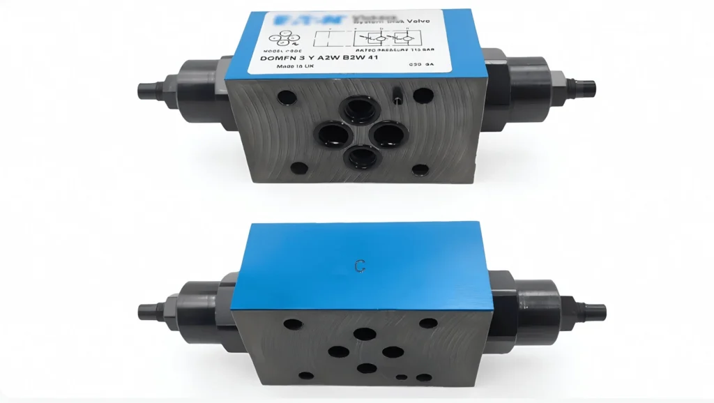
A check valve permits flow in one direction only and blocks reverse flow. Simple, reliable, and essential, check valves are used in:
- Pump isolation — preventing backflow through an idle pump in dual-pump systems
- Manifold protection — blocking reverse surges from actuators
- Pilot circuits — directing pilot signals
Pilot-to-open check valves (hydraulic locks) allow reverse flow only when pilot pressure is applied, used for load holding on cylinders.
Cartridge / Logic Valves
Cartridge valves—also called logic valves—are insertable valve elements seated in a manifold cavity. They come in two families:
- Screw-in cartridge valves (threaded, typically rated 210–420 bar) for compact integrated manifolds
- 2/2 logic cartridges (cover-controlled, rated to 350 bar and beyond) for high-flow industrial systems
Cartridge valves are increasingly the default choice for OEM manifolds because they:
- Handle high flow in a compact envelope (a single 32 mm logic cartridge can pass 300+ L/min)
- Allow custom logic combinations via control covers
- Reduce leak points and plumbing compared to pipe-mounted valves
- Lower weight in mobile equipment
The trade-off is manifold design complexity: cartridge systems require careful cavity machining and hydraulic logic design, typically done with specialized CAD tools.
Solenoid Valves
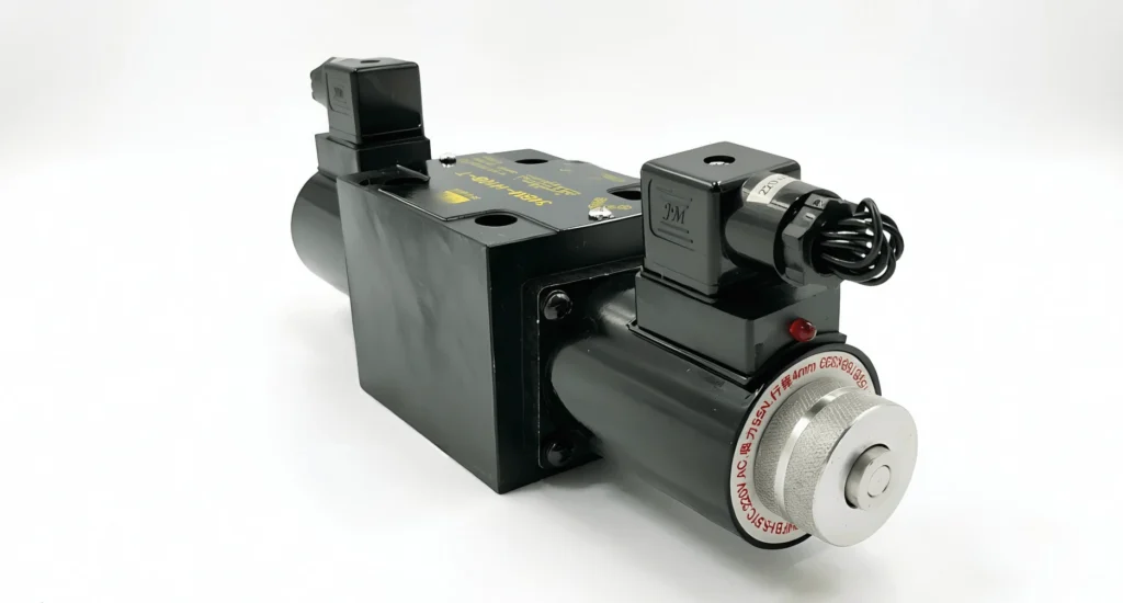
A solenoid valve is a directional valve actuated by an electromagnetic solenoid. They enable electrical control of hydraulic functions and are the building block of automated hydraulic systems.
- Wet-pin solenoids (armature bathed in oil) run cooler and quieter than dry-pin designs and dominate modern industrial valves
- AC solenoids switch faster but draw high inrush current and can burn out if the spool jams
- DC solenoids are more forgiving and dominate modern PLC-driven systems
- Typical ratings: 12 VDC, 24 VDC, 110/230 VAC, with IP65 enclosures standard
Solenoid valves are usually specified as 4/3 or 4/2 configurations on ISO 4401 subplates (D03/D05/D07/D08 sizes).
Proportional Valves
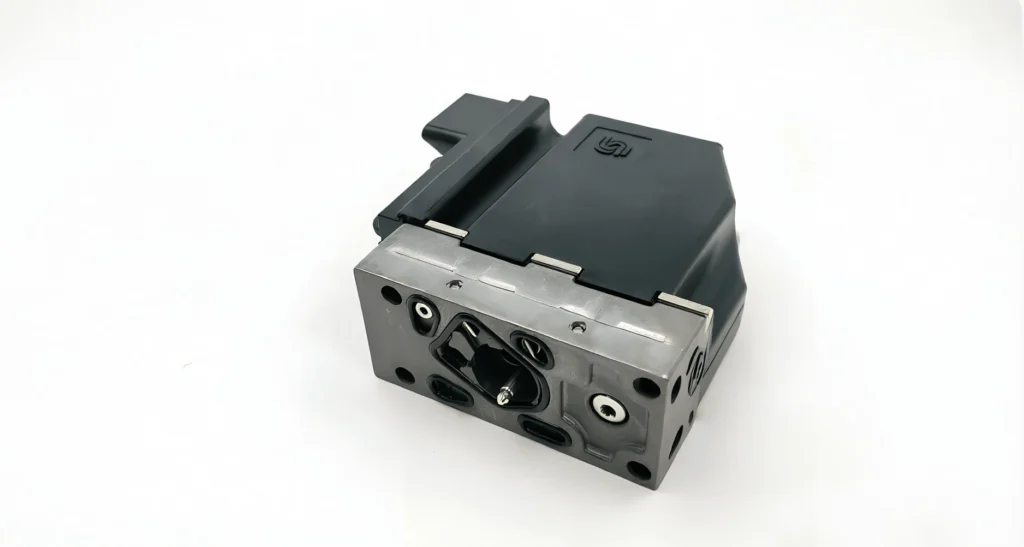
Proportional valves use a controlled-current solenoid to position the spool proportionally, rather than fully on/off. This enables variable flow and pressure control under electrical command.
- Stepless control of actuator speed and force
- Typical hysteresis: 3–6% without feedback, <1% with spool-position feedback (LVDT)
- Response time: tens of milliseconds—suitable for most industrial motion control
- Pressure range: typically up to 315 bar, flow from a few L/min to several hundred
Proportional valves are the workhorse of modern industrial automation—presses, injection molding, steel mills—where repeatable, controllable motion is required but the cost and sensitivity of servo valves is not justified.
Servo Valves
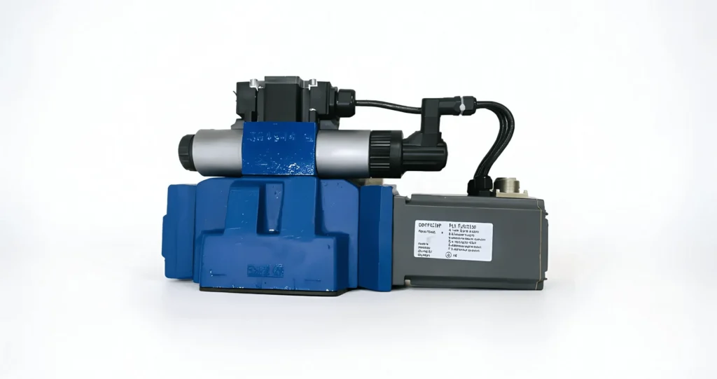
Servo valves are the highest-precision hydraulic control elements. They use a torque motor and nozzle-flapper or jet-pipe first stage to drive a spool with closed-loop position feedback, delivering:
- Frequency response above 100 Hz (vs tens of Hz for proportional valves)
- Hysteresis typically <0.5%
- Resolution is measured in fractions of a percent of stroke
Servo valves are used in flight simulators, fatigue test rigs, robotics, and aerospace actuators where dynamic performance matters more than cost. They demand exceptionally clean fluid (ISO 4406 15/13/10 or cleaner) and represent the most demanding valve category to specify and maintain.
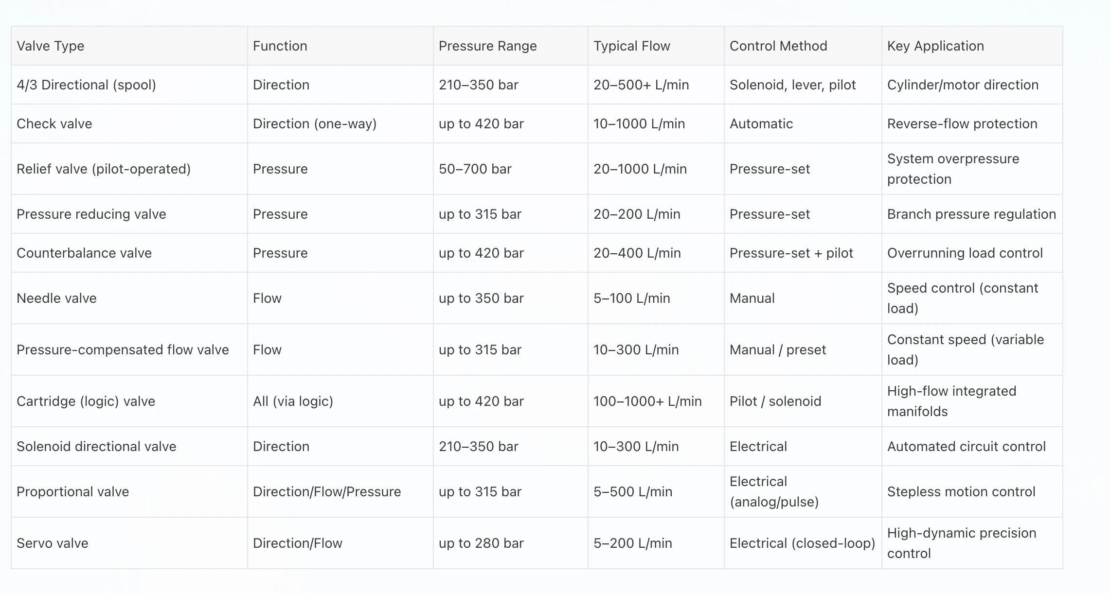
Hydraulic Valve Comparison Table
Actuation Methods Compared
| Actuation | Response Time | Cost | Best For | Limitation |
|---|---|---|---|---|
Manual (lever/pedal) |
Operator-limited |
Low |
Mobile equipment, simple machines |
No automation, depends on operator |
Mechanical (cam/roller) |
Fast |
Low |
Fixed-cycle machinery |
Limited to mechanical sequences |
Solenoid (electrical) |
20–80 ms |
Medium |
Automated systems, PLC control |
Limited force on large spools |
Pilot (hydraulic) |
30–150 ms |
Medium-High |
High-flow valves, remote contro |
Needs pilot pressure source |
Electro-hydraulic |
30–150 ms |
High |
Large-flow automated systems |
Pilot + solenoid combined |
Mounting Standards: ISO 4401 / CETOP & NFPA
| Standard | Region | Common Sizes |
|---|---|---|
ISO 4401 (CETOP RP121H) |
Europe / international |
NG6 (CETOP 03), NG10 (CETOP 05), NG16 (CETOP 07), NG25 (CETOP 08) |
NFPA D03/D05/D07/D08 |
North America |
Equivalent to CETOP 03/05/07/08 |
A valve marked “ISO 4401-03” (NG6) will mount on any CETOP 03 subplate worldwide. This interchangeability is why specifying the mounting pattern is the first procurement decision—everything else (port size, bolt pattern, flow capacity) follows from it.
For cartridge valves, the relevant cavity standards are ISO 7368 (logic cartridge cavities) and SAE J1926 / ISO 11926 for threaded cartridge cavities.
Pressure & Flow Rating Guide
Hydraulic valves must be sized so that:
- Rated pressure ≥ maximum system pressure, including pressure spikes (relief valve setting + ~25% spike margin)
- Rated flow ≥ maximum continuous flow at an acceptable pressure drop (ΔP)
Pressure drop across a valve is energy converted to heat. An oversized valve has low ΔP but a higher cost; an undersized valve runs hot and wastes energy. A common engineering target is ΔP ≤ 5 bar at rated flow for directional valves.
| System Type | Typical Valve Pressure Rating | Common Flow Range |
|---|---|---|
Light industrial / mobile (gear pump) |
210–250 bar |
20–120 L/min |
Medium industrial (piston pump) |
315 bar |
60–300 L/min |
Heavy industrial / press |
350 bar |
200–1000 L/min |
High-pressure (bolt tensioning, jacking) |
700 bar |
1–20 L/min |
Common Hydraulic Valve Failures
Valve failures rarely occur in isolation—they are usually symptoms of upstream contamination or improper specification. The most common failure modes are:
Valve Sticking / Sluggish Shift
- Causes: Contamination lodged in spool clearances, varnish from degraded oil, corrosion
- Symptoms: Delayed or incomplete shift, intermittent operation, solenoid burnout
- Most affected: Spool-type directional valves, pilot-operated relief valves
Internal Leakage
- Causes: Spool wear, scored bore, eroded poppet seat
- Symptoms: Drift under load, loss of holding force, reduced efficiency, overheating
- Most affected: Directional valves with worn spools, load-holding check valves
Solenoid Failure
- Causes: Coil burnout from jammed spool (AC), voltage drops, environmental ingress
- Symptoms: Valve fails to shift, audible hum, overheated coil
- Most affected: Solenoid directional valves, especially AC types
Pressure Instability
- Causes: Relief valve chatter, incorrect sizing, contaminated pilot orifice
- Symptoms: Pressure fluctuation, audible buzzing, unstable actuator motion
- Most affected: Pilot-operated relief valves, reducing valves
External Leakage
- Causes: Damaged seals, loose mounting, overpressurization
- Symptoms: Visible oil at the valve body, dripping from the subplate interface
- Most affected: Any valve with degraded static seals
Troubleshooting Guide
| Symptom | Likely Valve-Related Causes | Diagnostic Action |
|---|---|---|
Cylinder won’t move |
DCV not shifting; solenoid dead; pilot pressure low |
Check solenoid indicator, measure pilot pressure, inspect spool motion |
Cylinder drifts under load |
Internal leakage in DCV or load-holding check valve |
Isolate valve, check for bypass; replace worn spool or check valve |
Pressure won’t reach setpoint |
Relief valve stuck open or set too low; pump worn; reducing valve mis-set |
Measure pump output; verify relief setting; inspect relief valve |
Pressure fluctuates |
Relief valve chatter; air in system; contaminated pilot orifice |
Bleed air; clean pilot orifice; check for restricted suction |
Actuator speed slow |
Flow control mis-set; clogged orifice; valve undersized |
Verify flow control setting; measure flow; check ΔP across valve |
Valve runs hot |
Excessive ΔP from undersizing; continuous throttling; internal leakage |
Measure ΔP; verify valve sizing; consider proportional valve upgrade |
Solenoid burns out |
Spool jam; AC solenoid held in shifted position; low voltage |
Inspect spool free motion; check supply voltage; consider DC solenoid |
How to Select the Right Hydraulic Valve
A structured selection process prevents both over-engineering (paying for capability you don’t need) and under-engineering (premature failure). Use this sequence:
1. Define the Function
Determine whether the valve must control direction, pressure, or flow (or a combination, as with proportional valves). This fixes the valve family.
2. Establish Operating Parameters
- Maximum sustained pressure (and expected spikes)
- Maximum and minimum flow
- Fluid type and viscosity grade (ISO VG 32 / 46 / 68)
- Cleanliness target (ISO 4406 code)
- Ambient and fluid temperature range
3. Choose the Configuration
For directional valves: ports/positions, center configuration (open, closed, tandem, float). For pressure valves: direct-acting vs pilot-operated. For flow valves: compensated vs non-compensated.
4. Select Actuation
Manual, mechanical, solenoid, pilot, or electro-hydraulic—based on control system architecture, response requirement, and available pilot/electrical supply.
5. Confirm Mounting Interface
ISO 4401 (CETOP) size for subplate valves, or cartridge cavity standard for integrated manifolds. Confirm port size and bolt pattern.
6. Verify Pressure Drop
At your operating flow, confirm ΔP is within an acceptable range (typically ≤5 bar). Excessive ΔP causes heating; insufficient flow path causes cavitation.
7. Evaluate Contamination Tolerance
Proportional and servo valves require ISO 4406 16/14/11 or cleaner. If your system filtration cannot achieve this, specify a more contamination-tolerant valve or upgrade filtration.
8. Procurement Considerations
- Lead time for spare parts and replacement coils
- Availability of equivalent valves from multiple manufacturers (ISO/CETOP interchangeability)
- Documentation: symbol, cross-section, performance curves
- Warranty and field-support network
Maintenance Best Practices
- Maintain oil cleanliness to the level required by your most sensitive valve (often the determining factor in valve life)
- Replace filters on schedule, monitoring differential pressure indicators
- Verify pressure settings annually with a calibrated gauge—drift indicates spring fatigue or contamination
- Inspect solenoid operation periodically; sluggish shifting precedes most failures
- Monitor temperature—sustained operation above 60°C accelerates oil degradation and seal hardening
- Keep spare coils and solenoids for critical valves; solenoid failure is the most common downtime cause in automated systems
- Sample oil quarterly for particle count, water content, and viscosity; trend the results
A useful industry benchmark: in systems with well-controlled contamination (ISO 4406 18/16/13 or better), hydraulic valve life routinely exceeds 10,000 operating hours. In systems at ISO 22/20/17 or worse, valve failures can appear within 2,000 hours.
Industrial Applications
Different industries favor different valve technologies based on pressure, flow, duty cycle, and control requirements:
| Industry | Dominant Valve Types | Why |
|---|---|---|
Construction equipment |
Cartridge valves, 4/3 tandem-center DCVs |
High flow, compact manifold, mobile duty |
Agricultural machinery |
Solenoid DCVs, counterbalance valves |
Cost-sensitive, moderate pressure, automated functions |
Manufacturing / presses |
Proportional valves, pilot-operated relief valves |
Precise force/speed control, high cycle counts |
Mining equipment |
Cartridge logic valves, relief valves |
High pressure, harsh environment, high flow |
Marine hydraulics |
Stainless/specialty DCVs, proportional valves |
Corrosion resistance, precise positioning |
Oil & gas |
Cartridge valves, high-pressure relief valves |
350–700 bar systems, compact integrated manifolds |
Wind energy |
Proportional valves for pitch/brake |
Precise control, reliability-critical duty |