
Introduction
Every hydraulic actuator needs a way to choose its direction. A hydraulic directional valve does that job. It routes pump flow to one side of a cylinder or motor and opens the return path from the other side.
This guide covers positions and ways, spool center types, actuation methods, and sizing rules. We write it for engineers who specify and fix these valves in the field. Real numbers follow, including pressure bands, flow ratings, ISO 4401 sizes, and shift times.
What is a Hydraulic Directional Valve
A hydraulic directional valve controls the fluid path between pump, actuator, and tank. It picks which port sees pressure and which port drains. Shift it one way and a cylinder extends. Shift it the other way and the cylinder retracts.
Most builds use a cylindrical spool inside a precision-bored body. Lands on the spool block ports, and grooves connect them. Moving the spool changes which ports line up.
People shorten the name to DCV. You will also see “directional control valve.” The terms mean the same thing here. This article treats the DCV as the component that reverses an actuator, distinct from a diverter that selects between two separate circuits.
How a Hydraulic Directional Valve Works
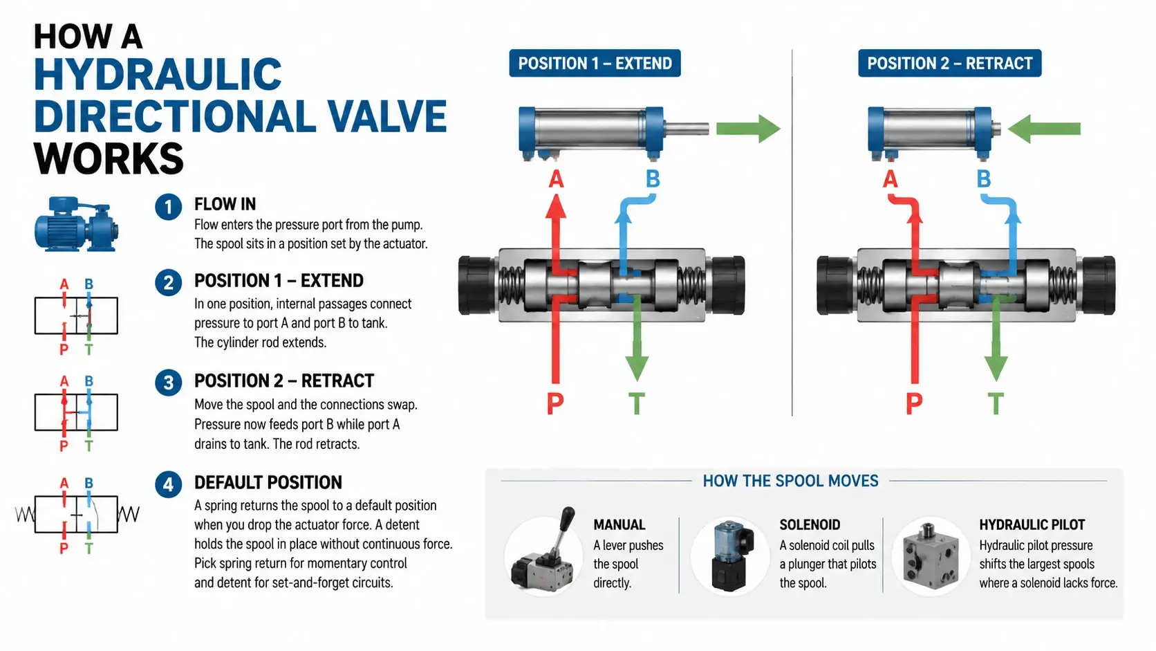
Flow enters the pressure port from the pump. The spool sits in a position set by the actuator. In one position, internal passages connect pressure to port A and port B to tank. The cylinder rod extends.
Move the spool and the connections swap. Pressure now feeds port B while port A drains to the tank. The rod retracts. The valve has changed the actuator direction without reversing the pump.
The spool needs a force to move it. A manual lever pushes it directly. A solenoid coil pulls a plunger that pilots the spool. The hydraulic pilot pressure shifts the largest spools where a solenoid lacks force.
A spring returns the spool to a default position when you drop the actuator force. A detent holds the spool in place without continuous force. Pick spring return for momentary control and detent for set-and-forget circuits.
Positions and Ways Explained
Valve shorthand reads as “positions/ways.” Positions count the spool stops. Ways to count the working ports. A 4/3 valve has four ports and three spool positions.
A 2/2 valve is an on-off isolator with one port in and one out. A 3/2 valve adds a third port for exhaust or return. These small valves pilot other valves or run single-acting cylinders.
The 4/2 valve runs a double-acting cylinder in two positions: extend and retract. It has no neutral. The 4/3 valve adds a center position, and that center does most of the engineering work.
Most mobile and industrial circuits use a 4/3 valve. The two end positions reverse the actuator. The center position decides what happens at idle, which is where the pump and the load meet the valve.
Spool Center Configurations
The center position sets the idle behavior. Get it wrong and the pump deadheads, the actuator drifts, or the hose spikes on shift. Match the center to the pump type and the hold requirement.
| Center Type | Pump Path | Actuator Ports A/B | Use When |
|---|---|---|---|
Closed center |
Blocked |
Blocked |
Hold load, variable pump |
Open center |
Pump to tank |
All connected |
Fixed pump, free actuator |
Tandem center |
Pump to tank |
Blocked |
Fixed pump, hold load |
Float center |
Blocked |
A and B to tank |
Motor freewheel, cylinder drift |
A closed center blocks every port. The actuator holds its position. The pump deadheads against the valve, so pair a closed-center valve with a pressure-compensated or variable pump.
An open center connects the pump to the tank at idle. The pump unloads through the valve. Pair this type with a fixed-displacement gear pump, the classic open-center mobile circuit.
A tandem center sends pump flow to the tank but blocks the actuator ports. The load holds while the pump unloads. This center fits a fixed pump that must hold a suspended load.
A float center blocks the pump and connects A and B to the tank. The actuator costs. Use it on a loader bucket so the bucket can follow the ground contour, or on a motor that must freewheel.
Actuation Methods
Manual Lever
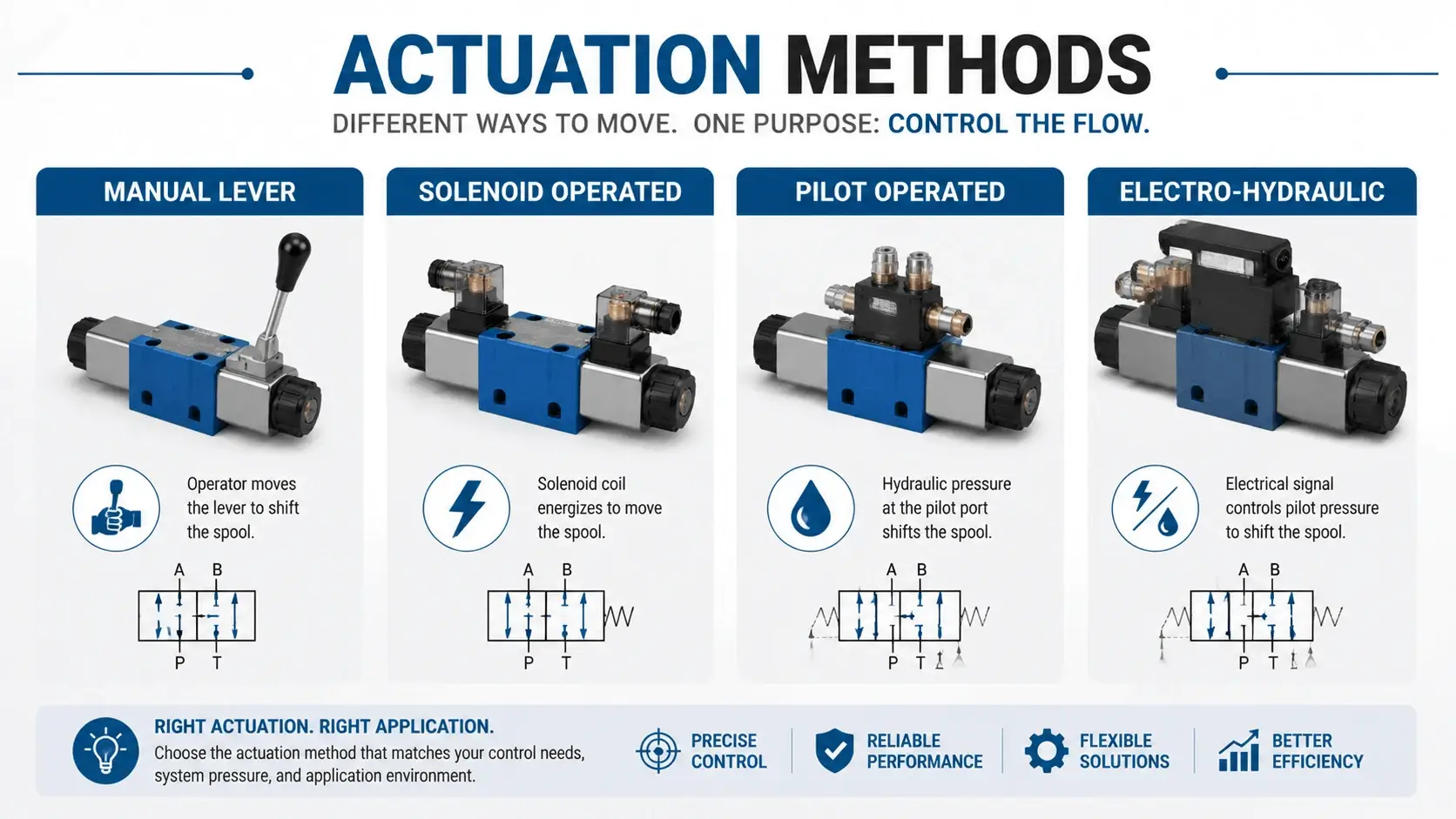
A hand lever moves the spool through a link. The operator controls shift speed by feel. These valves suit low-cycle work where someone stands at the machine.
Ratings run 210 to 350 bar with flows from 20 to 80 L/min. Bodies use cast iron or ductile iron. Threads follow SAE J1926 or ISO 6149 on mobile equipment.
Solenoid Operated
An electric coil shifts the spool. Mobile valves use 12 or 24 V DC coils. Industrial valves run 24 V DC or 110/230 V AC. Shift time lands between 15 and 60 ms.
Wet-pin coils sit in oil, run cooler, and outlast dry-pin types. Add a surge suppressor across the coil to protect the controller. Solenoid force is small, so these valves cap out near 100 L/min.
Pilot Operated
A small solenoid or manual valve routes pilot pressure to shift a large main spool. The main spool carries the full flow. This design handles 100 to 300 L/min and pressures to 350 bar.
Pilot ratio and drain routing matter as much as the main spool. Plumb the case drain to the tank below fluid level. A drain above level pulls air and cavities the pilot.
Electro-Hydraulic
A solenoid drives the pilot stage, and hydraulic pressure drives the main stage. This gives electric control at high flow. You get the response of a solenoid valve with the capacity of a pilot valve.
Key Specifications of Hydraulic Directional Valve
| Spec | Mobile DCV | Industrial DCV |
|---|---|---|
Pressure |
210 to 350 bar |
350 to 420 bar |
Flow |
20 to 100 L/min |
100 to 700 L/min |
Voltage |
12/24 V DC |
24 V DC, 110/230 V AC |
Mounting |
In-line, cartridge |
ISO 4401 subplate |
Cleanliness |
ISO 4406 19/17/14 |
ISO 4406 18/16/13 |
Ports |
SAE J1926, ISO 6149 |
ISO 4401, ISO 6149 |
Pressure rating sets the upper safe working pressure. Derate 15 to 25 percent for shock loads. Flow rating matters more than pressure for sizing, because excess velocity washes out the spool.
Spool configuration drives circuit behavior. A 2-position valve has no neutral. A 3-position valve adds a center that blocks, floats, or unloads the pump.
Sizing by ISO 4401 / CETOP
Size the valve for flow first, pressure second. Velocity through the body should stay under 6 m/s for continuous duty. Higher velocity erodes the spool and heats the oil.
Use this formula for port velocity. v = Q x 21.22 / d squared. Q is flow in L/min, and d is port diameter in mm. For 60 L/min through a 12 mm port, v works out to 8.8 m/s. That exceeds the limit, so step up to a 16 mm port.
Map flow to ISO 4401 sizes. NG6 handles about 60 L/min, NG10 about 120, NG16 about 300, and NG25 about 700. Pick the smallest size that keeps velocity under 6 m/s.
Pressure drop across the valve wastes energy and heats the oil. Most catalogs list delta P at a reference flow. Scale it with the square of flow. A catalog that lists 2 bar at 40 L/min will read 8 bar at 80 L/min.
Directional vs Proportional vs Servo
A hydraulic directional valve is an on-off device. The spool snaps fully open or fully closed. The flow goes to the actuator at full pump output, or it stops.
A proportional valve meters flow between those extremes. The spool moves to a partial position, so the actuator speed varies with command. Pay for a proportional valve when you need smooth acceleration or remote speed control.
A servo valve closes a feedback loop on position or velocity. It measures with high precision and fast response. Servo valves suit test rigs and motion-control machines where a directional valve cannot hold the tolerance.
The boundary is cost and need. A directional valve costs less and lasts longer in dirty oil. Step up to proportional only when the on-off motion will not meet the cycle.
Selection Guide
Start with the actuator you want to reverse. List the pump flow, the working pressure, and the cycle rate. Then match these against valve ratings.
Pick the center type from the pump. Closed center with a variable pump. Open or tandem center with a fixed pump. Add a float if the actuator must coast.
Pick the actuation from the cycle. Manual for low-cycle work at the machine. Solenoid for electric control under 100 L/min. Pilot or electro-hydraulic above that.
Pick the size from the flow. Keep port velocity under 6 m/s. Map to ISO 4401 NG6, NG10, NG16, or NG25. Verify the port threads against your fittings, since SAE J1926 and ISO 6149 do not interchange.
Common Applications
Mobile Equipment
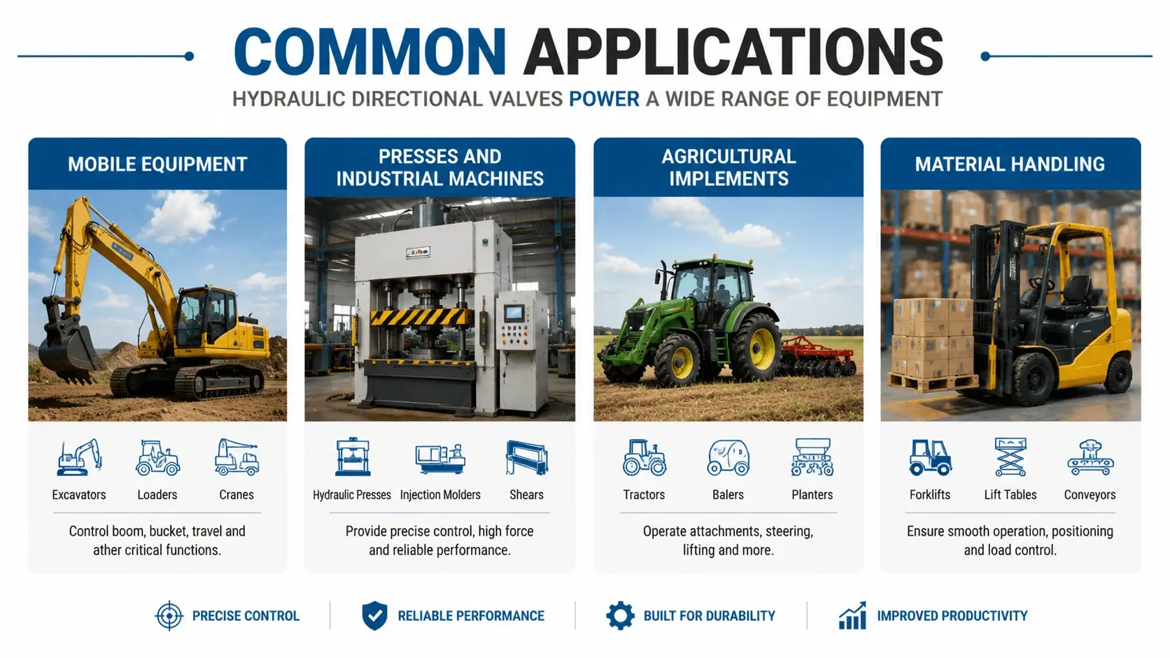
Loaders, backhoes, and telehandlers run 4/3 valves on every boom and cylinder function. Open-center valves pair with the gear pump. Closed-center valves pair with the variable piston pump.
Presses and Industrial Machines
A shop press uses a 4/3 valve to extend, hold, and retract the ram. Tandem center unloads the pump during the hold. Closed center holds the ram under a pressure-compensated pump.
Agricultural Implements
Tractors run remote valves on the rear for implements. ISO 6149 ports and a 19/17/14 cleanliness target fit this duty. Float center lets a planter follow ground contour.
Material Handling
Forklifts and lift tables use 4/3 valves on the lift cylinder. Closed center holds the load. A cross-port relief absorbs the shock when the spool shifts under load.
Common Problems and Troubleshooting
| Symptom | Likely Cause | Action |
|---|---|---|
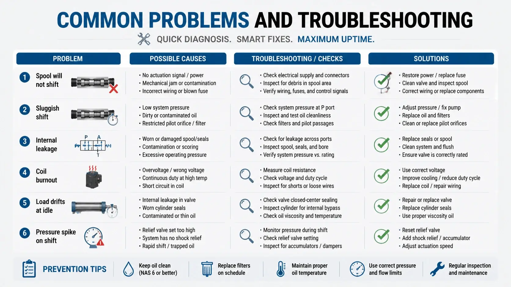
Spool will not shift |
Contamination, bent rod |
Flush, inspect rod |
Sluggish shift |
Cold oil, wrong viscosity |
Check ISO VG grade |
Internal leakage |
Worn spool bore |
Re-hone or replace |
Coil burnout |
Wrong voltage, stuck spool |
Match voltage, free spool |
Load drifts at idle |
Wrong center type |
Fit tandem or closed center |
Pressure spike on shift |
No cross-port relief |
Add relief across A and B |
Contamination causes most failures. A single hard particle wedged between the spool and bore scores the surface. Once scored, the bore leaks and the spool sticks.
Cold oil also slows the shift. Most mobile systems run ISO VG 32 or 46 hydraulic oil. Check the viscosity grade against your operating temperature before you blame the valve.
Maintenance
Pull an oil sample every 500 hours for mobile equipment and every 2000 hours for industrial. Target ISO 4406 19/17/14 for mobile and 18/16/13 for industrial. A drift toward 21/19/16 means the filter needs attention.
Log spool shift time during planned downtime. A shift that slows from 30 ms to 80 ms warns of build-up before it fails. Trend the data over time. A single reading will not show the slide.
Replace solenoid coils in pairs when one fails early. The second coil usually follows within weeks. Keep a spare on the shelf rather than ordering after the second failure.
Inspect the detent and centering springs when you service the valve. A worn spring lets the spool drift under shock. Replace the spring kit before the spool loses its position in service.
FAQ
What is a hydraulic directional valve?
A hydraulic directional valve controls the fluid path between the pump, the actuator, and the tank. It selects which port sees pressure and which port drains, so a single pump can extend and retract a cylinder or reverse a motor.
How does a hydraulic directional valve work?
The valve uses a sliding spool inside a bored body. In one position, passages connect pressure to port A and port B to the tank. Move the spool and the connections swap, so the actuator reverses. A manual lever, solenoid, or hydraulic pilot moves the spool.
What is the difference between 4/2 and 4/3 directional valves?
A 4/2 valve has four ports and two spool positions, extend and retract, with no neutral. A 4/3 valve adds a center position that blocks, floats, or unloads the pump at idle. The 4/3 valve suits circuits that need a defined idle state.
What is the difference between open-center and closed-center valves?
An open center valve connects the pump to the tank at idle, which suits a fixed-displacement pump. A closed center valve blocks every port at idle, which suits a pressure-compensated or variable pump. The center type must match the pump.
How do I size a hydraulic directional valve?
Size for flow first. Keep port velocity under 6 m/s for continuous duty using v = Q x 21.22 / d squared. Then map the flow to an ISO 4401 size, NG6 to NG25. Check the pressure rating and derate 15 to 25 percent for shock loads.
Why is my hydraulic directional valve sticking?
Contamination is the most common cause. A hard particle wedged between the spool and the bore scores the surface. Pull an oil sample and target ISO 4406 19/17/14 for mobile or 18/16/13 for industrial. Cold oil or the wrong viscosity also slows the shift.
Should I choose a solenoid or a pilot-operated directional valve?
Use a solenoid valve for electric control under 100 L/min. Use a pilot-operated valve above 100 L/min or 350 bar, where a solenoid lacks the force to move the spool. Add electro-hydraulic actuation when you need electric control at high flow.
Conclusion
A hydraulic directional valve reverses an actuator by routing pump flow to one side and opening the return from the other. Pick the positions and ways from the actuator motion. Pick the spool center from the pump type and the hold requirement. Pick the actuation from the cycle and the flow.
Size the valve for port velocity first, then pressure. Keep the flow under 6 m/s for continuous duty. Add a cross-port relief to absorb shift spikes. Match the center to the pump so the circuit unloads or holds the way you expect.
Hold the oil clean. ISO 4406 19/17/14 for mobile and 18/16/13 for industrial keeps the spool shifting fast and the bore leak-free. Trend the shift time, and you catch wear before it becomes downtime.