
Introduction
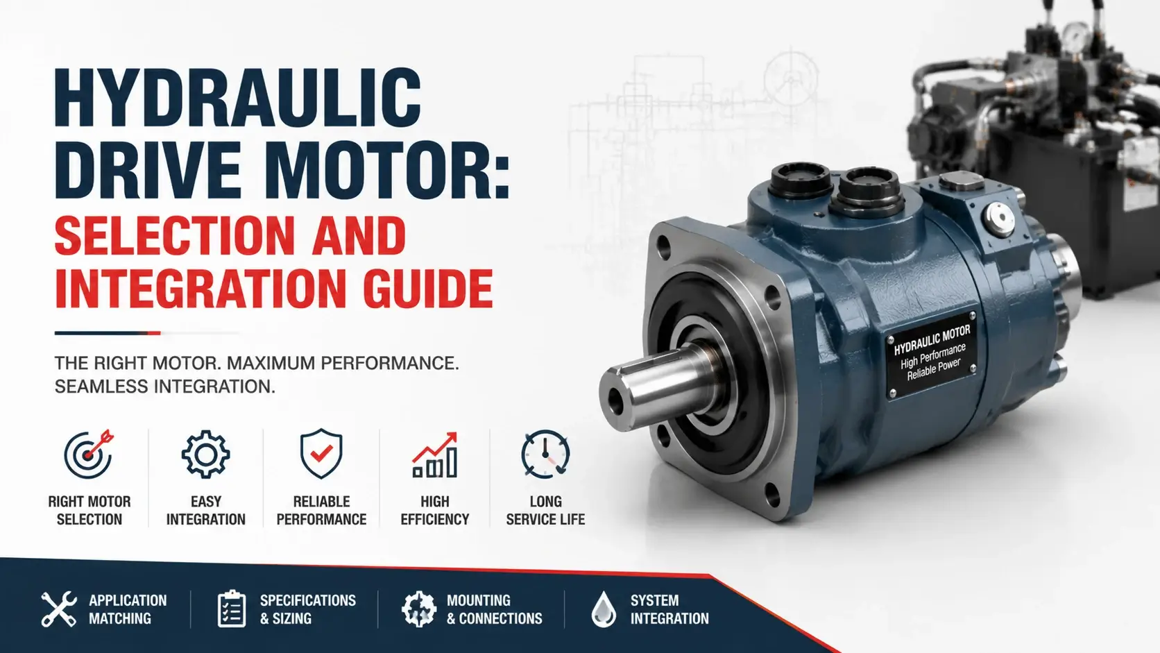
A hydraulic drive motor turns fluid power into the rotary motion a machine needs to move. You find one on a winch drum, a slewing ring, a travel track, or a conveyor head shaft. The motor sits where the hydraulic circuit meets the load.
Most catalogs list hydraulic motors by type and displacement. That gets you halfway. A drive motor has to fit a real load, mount to a real frame, stop safely, and hold against gravity. The specifying work separates a motor that runs from one that drives well.
This guide covers how to engineer the motor into a working rotary drive. It works through drive dynamics, mounting standards, speed control, integrated accessories, and the four drive applications you see most. The goal is a motor that matches the load, not just one that fits the port size.
What is a Hydraulic Drive Motor
A hydraulic drive motor is a rotary actuator that drives a load through a shaft. Pressurized oil enters, pushes internal gears, vanes, or pistons, and turns the output shaft. The shaft delivers torque to whatever you couple it to.
Every hydraulic motor does this. The difference here is emphasis. A drive motor gets specified, mounted, braked, and controlled as part of a working drive. You ask what load it drives, how it stops, and how it survives the cycle.
That framing matters because the same displacement motor fails in one machine and lasts 10,000 hours in another. The load, the mounting, the control method, and the accessories decide the outcome. Pick the motor for the drive, not the catalog page.
How a Hydraulic Drive Motor Works
Oil enters the motor inlet at working pressure and pushes against the internal working parts. Gears, vanes, or pistons convert that push into a turning moment about the shaft. Spent oil leaves the outlet at near-tank pressure.
Three numbers set the output. Displacement in cc per rev fixes the torque per bar of pressure. Pressure in bars fixes how hard the shaft twists. Flow in liters per minute fixes how fast the shaft spins. Change one, and the drive behaves differently.
The relief valve caps pressure and protects the circuit. A directional valve or a reversing pump sets the rotation. To stop a driven load, you cut the flow, hold the pressure, or let a brake clamp the shaft. The motor itself just responds to what the circuit feeds it.
Drive Dynamics: Torque, Inertia, and Acceleration
A drive motor does not just hold a steady speed. It starts, stops, reverses, and survives shock. Four torque values define the job.
Breakaway torque overcomes static friction and gets the load moving. It runs 1.2 to 2 times the running torque on most machines, higher on machines that sit idle and rust. Running torque holds the load at speed. Peak torque handles the moment a load slams or a tooth catches. Stall torque is what the motor delivers at zero speed before the relief valve dumps.
Inertia matters as much as torque. A high-inertia load needs torque to accelerate, not just to hold. The acceleration time equals load inertia times speed change, divided by the net accelerating torque. Size the motor for breakaway and acceleration. Then check it against running and stall. Skip this and the drive stalls on every start-up.
Mounting, Shaft, and Port Standards
A drive motor only works if it bolts up and lines up. Three standards decide that.
Mounting flanges follow ISO 3019-1 for metric two-hole and four-hole flanges. SAE J744 covers the inch-series flanges common on mobile equipment. Match the flange to the housing bore and bolt pattern before you order. A flange that almost fits ruins the alignment.
Shaft options fall into three groups. Straight-keyed shafts suit low to moderate torque. Splined shafts, per ISO 14 or DIN 5480, handle high torque and frequent reversal without fretting. Tapered shafts with a key and drawnut give the most secure fit for heavy shock loads. Couple the shaft type to the load’s shock and reversal, not to the price.
Ports follow SAE J1926 straight-thread, ISO 6149 metric, or BSP. Each needs its own seal and torque value. Mixing standards leaks. The case drain port is easy to forget. It matters most on piston motors, where blocked drain pressure blows the shaft seal.
Speed Control Methods for a Hydraulic Drive Motor
You control the motor in three ways, and each changes the hardware.
Meter-in throttling uses a flow control valve between the pump and the motor. It is cheap and simple. The wasted pressure drops across the valve as heat. Throttling suits low-power drives where efficiency matters less than cost.
Variable-displacement control uses a variable pump to set motor speed by changing flow. Pressure stays near the load demand, so the losses stay low. This is the standard method for closed-loop hydrostatic travel and winch drives. You pay for it in pump cost and control complexity.
Proportional electronic control pairs a proportional valve or an electronic variable pump with a speed sensor. The controller holds speed under varying load. High-end slewing and positioning drives use this when the load swings or the process needs repeatability. It costs the most and delivers the tightest control.
Integrated Drive Accessories
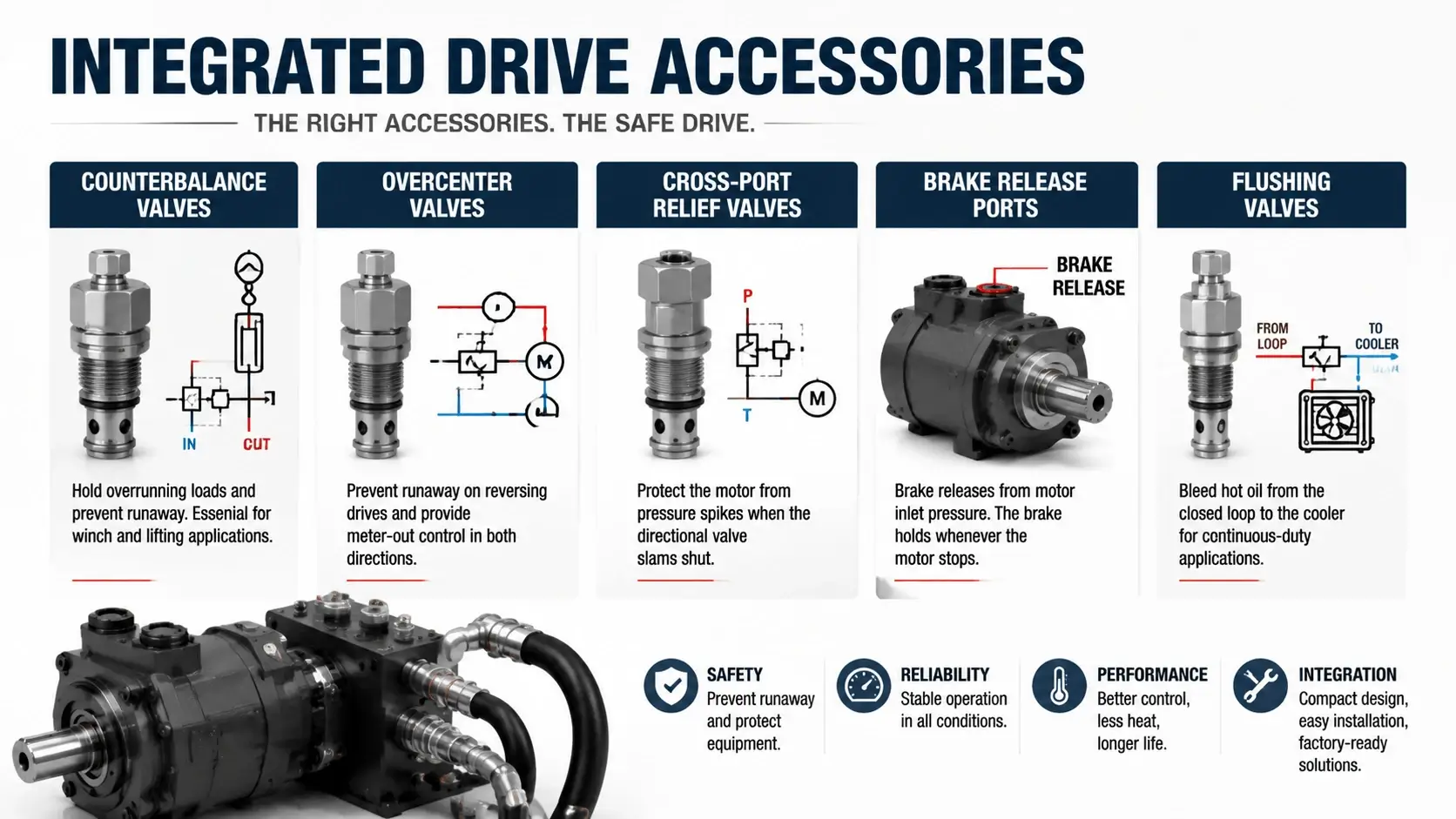
A bare motor on a shaft will not survive a real drive. The accessories make the drive safe.
Counterbalance valves hold overrunning loads and prevent runaway. A winch lowering a load needs one. The valve senses motor inlet pressure and opens metered flow to the outlet, holding back pressure against the load. Without it, the load free-falls.
Overcenter valves do the same job for reversing drives and add meter-out control in both directions. They suit slewing drives and any load that can drive the motor. Cross-port relief valves protect the motor from pressure spikes when the directional valve slams shut. Most integrated valve cartridges mount right in the motor ports.
Brake release ports matter on travel and winch drives. The brake releases from motor inlet pressure, so the brake holds whenever the motor stops. A flushing valve bleeds hot oil from the closed loop to the cooler in continuous-duty drives. Skip these and the drive works on the bench and fails in the field.
The Four Drive Applications

Four drive jobs cover most of what these motors do.
Slewing Drive
A slewing drive turns a house or a boom on a ring gear. The load swings, reverses, and holds position against wind and tilt. Overspeed on the down-swing is the main failure. Use an overcenter valve and size for breakaway plus wind torque. Slewing motors run at 200 to 350 bar and 5 to 60 rpm at the ring.
Traction Drive
A traction drive moves the machine on tracks or wheels. The load climbs, slips, and shocks on every rut. Stall torque decides if the machine climbs or stops. Closed-loop variable pumps feed axial piston or radial piston motors at 280 to 420 bar. Put a brake in line and a flushing valve on the loop.
Winch Drive
A winch drive pulls a load on a drum. Gravity helps on the way down and fights on the way up. The motor must hold full torque at zero speed without overheating. A counterbalance valve and a spring-applied brake do most of the safety work. Winch motors run radial piston for heavy low-speed service or axial piston for faster line speeds.
Conveyor and Feed Drive
A conveyor or feed drive moves material at steady speed. The load varies as product enters and leaves. Breakaway and peak torque from a jam decide the size. Gear or vane motors handle most of this work at 100 to 210 bar. Add a cross-port relief so a jam does not burst the line.
Common Drive Failures and How to Prevent Them
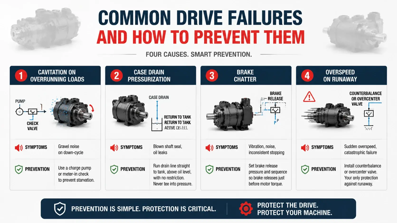
Most drive motor failures trace to four causes.
Cavitation on overrunning loads happens when the load drives the motor faster than the pump feeds it. The inlet starves, and the internals tear. A charge pump or a meter-in check stops it. Listen for gravel noise on the down-cycle.
Case drain pressurization on vertical drives blows the shaft seal. The drain line must return to the tank above the oil level with no restriction. Run the drain straight to the tank and never tee it into a pressurized return.
Brake chatter comes from a brake that releases too slowly or chatters against the load. Set the brake release pressure and sequence so the brake releases just before the motor produces torque.
Overspeed on the runaway is the fastest killer. A load dropping under gravity will spin a motor past its rated speed in seconds. The counterbalance or overcenter valve is the only thing between the load and a destroyed motor.
Selection and Specification Checklist
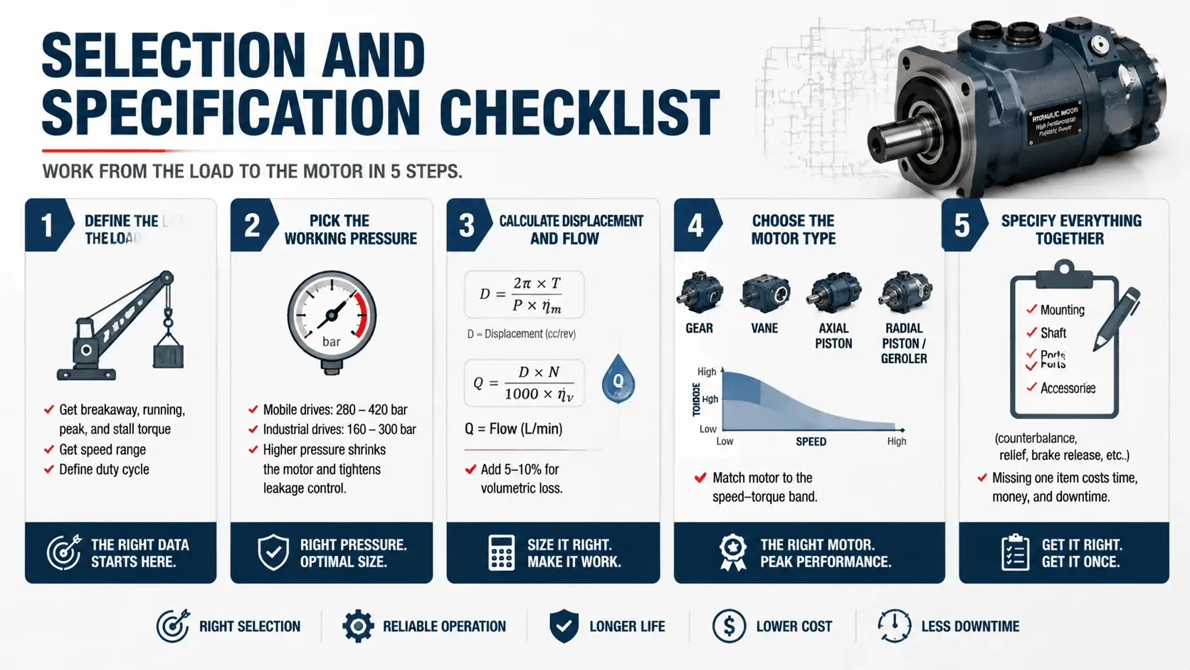
Work from the load to the motor in five steps.
Define the load. Get breakaway, running, peak, and stall torque, plus the speed range and the duty cycle. A drive that runs 10 percent of the time sizes differently from one that runs continuously.
Pick the working pressure. Mobile drives run 280 to 420 bar. Industrial drives run 160 to 300 bar. Higher pressure shrinks the motor and tightens the leakage control.
Calculate displacement from the breakaway torque and pressure. Then calculate flow from displacement and speed. Add 5 to 10 percent for volumetric loss.
Choose the motor type from the speed-torque band. High speed and moderate torque mean gear, vane, or axial piston. High torque at low speed means radial piston or geroler.
Specify the mounting, shaft, ports, and accessories on the same sheet. A motor ordered without the counterbalance valve costs you a second order and a week of downtime.
Maintenance for Drive Service
Fluid health decides motor life. Sample every 500 hours for particle count, viscosity, and water. Hold ISO 4406 to 20/18/15 for general drives and 18/16/13 for high-pressure piston motors.
Trend the case drain flow. A bucket and a stopwatch give you the number. A steady rise means internal wear is eating the displacement. Catch it before the motor loses breakaway torque.
Check the accessories when you check the motor. A counterbalance valve that drifts its setting lets the load creep. A brake that drags burns energy and heats the oil. Both fail slowly until they fail fast.
Inspect the coupling and shaft for fretting during teardown. Fretting means the shaft type was wrong for the shock load. Change the shaft specification, not just the motor.
FAQ
What is a hydraulic drive motor?
A hydraulic drive motor is a rotary actuator that drives a load through a shaft. Pressurized oil enters and turns the output shaft, which delivers torque to the machine.
What makes a drive motor different from any hydraulic motor?
The component is the same. The emphasis differs. You engineer the mounting, braking, speed control, and accessories together as a working drive, not just pick a displacement from a catalog.
How do you control the speed of the motor?
Three ways. Throttling with a flow control valve wastes pressure as heat but costs little. A variable-displacement pump sets speed by flow and keeps losses low. Electronic proportional control holds speed under varying load for the tightest result.
What accessories does the motor need?
Counterbalance or overcenter valves manage overrunning loads. Cross-port reliefs absorb shock. A brake with its release port holds position. A flushing valve cools continuous closed-loop duty. Most mount in the motor ports.
What causes the motor to fail?
Four causes lead. Cavitation on overrunning loads starves the inlet. Blocked case drain pressure blows the shaft seal. Overspeed on a runaway load destroys the internals. Contamination wears the working parts. Each is preventable with the right accessory and fluid care.
How do you size the motor for a drive?
Start with breakaway and acceleration torque, not running torque. Pick the pressure, calculate displacement, then flow. Match the motor type to the speed-torque band and specify the mounting and accessories on the same sheet.
Conclusion
A hydraulic drive motor earns its place at the point where fluid power meets the load. The component matters, but the specifying matters more. Get the drive dynamics, mounting, speed control, and accessories right. The motor then runs for thousands of hours. Get them wrong and no motor survives the duty cycle.