
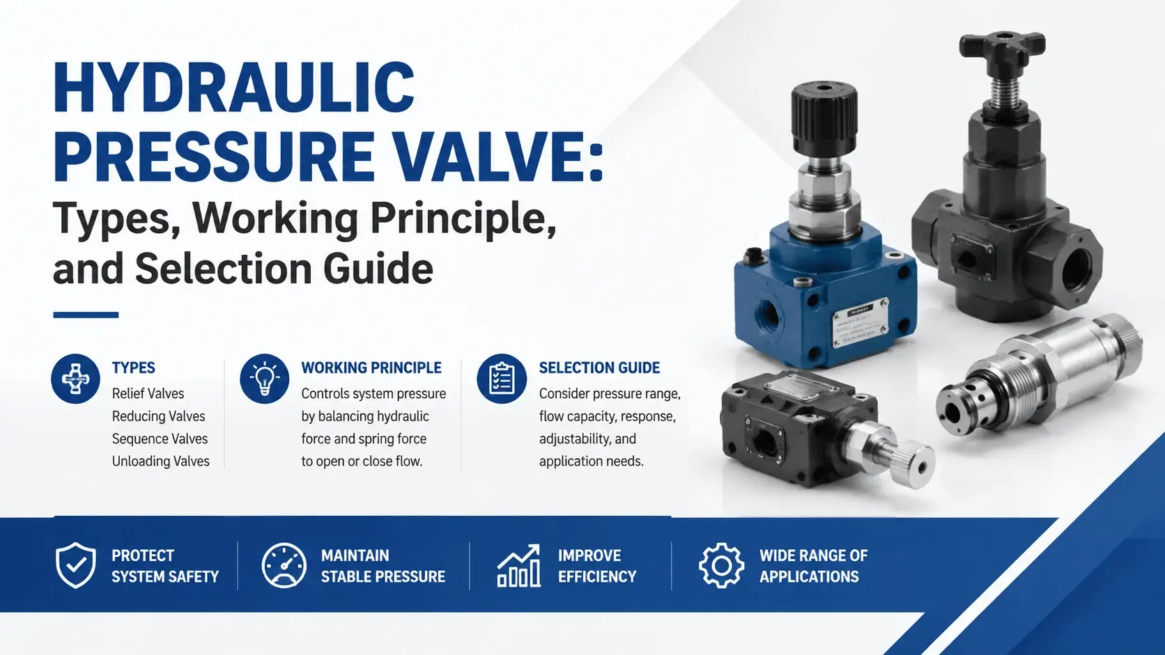
A hydraulic pressure valve sits at the heart of almost every fluid power circuit. It keeps pressures within safe limits, regulates actuator forces, and protects expensive components from damage.
Without properly selected pressure valves, pumps overpressurize, cylinders stall unpredictably, and systems overheat. This guide walks through the four main pressure valve types, explains how each one works, and shows you how to pick the right unit for your application.
What is a Hydraulic Pressure Valve?
A hydraulic pressure valve is a device that monitors and limits or regulates pressure at a specific point in a hydraulic circuit. Unlike directional valves, which steer fluid flow, or flow valves, which control speed, a pressure valve of this kind responds to the force exerted by the fluid itself. When pressure reaches a threshold, the valve shifts internally to open, close, or throttle a passage.
Pressure valves fall into two broad groups. Limiting valves (relief, sequence, counterbalance) stay normally closed and open only when pressure exceeds a set point. Regulating valves (pressure reducing) stay normally open and throttle down as outlet pressure rises. Understanding this split helps you place the right valve in the right location.
How Hydraulic Pressure Valves Work
Most pressure valves operate on a simple force-balance principle. A spring pushes against a poppet, spool, or cartridge. System pressure acts on an opposing area. When the pressure force exceeds the spring force, the internal element moves. That motion opens a path to tank (in a relief valve) or restricts flow (in a reducing valve).
The equation looks like this:
Spring Force equals Pressure times Area
Turn the adjustment screw clockwise and you increase spring force. The valve now opens at a higher pressure. Turn it counterclockwise, and the cracking pressure drops. Pilot-operated designs add a small pilot stage so that system pressure assists the spring. This arrangement gives better control at high flows but introduces a small delay in response.
Types of Hydraulic Pressure Valves
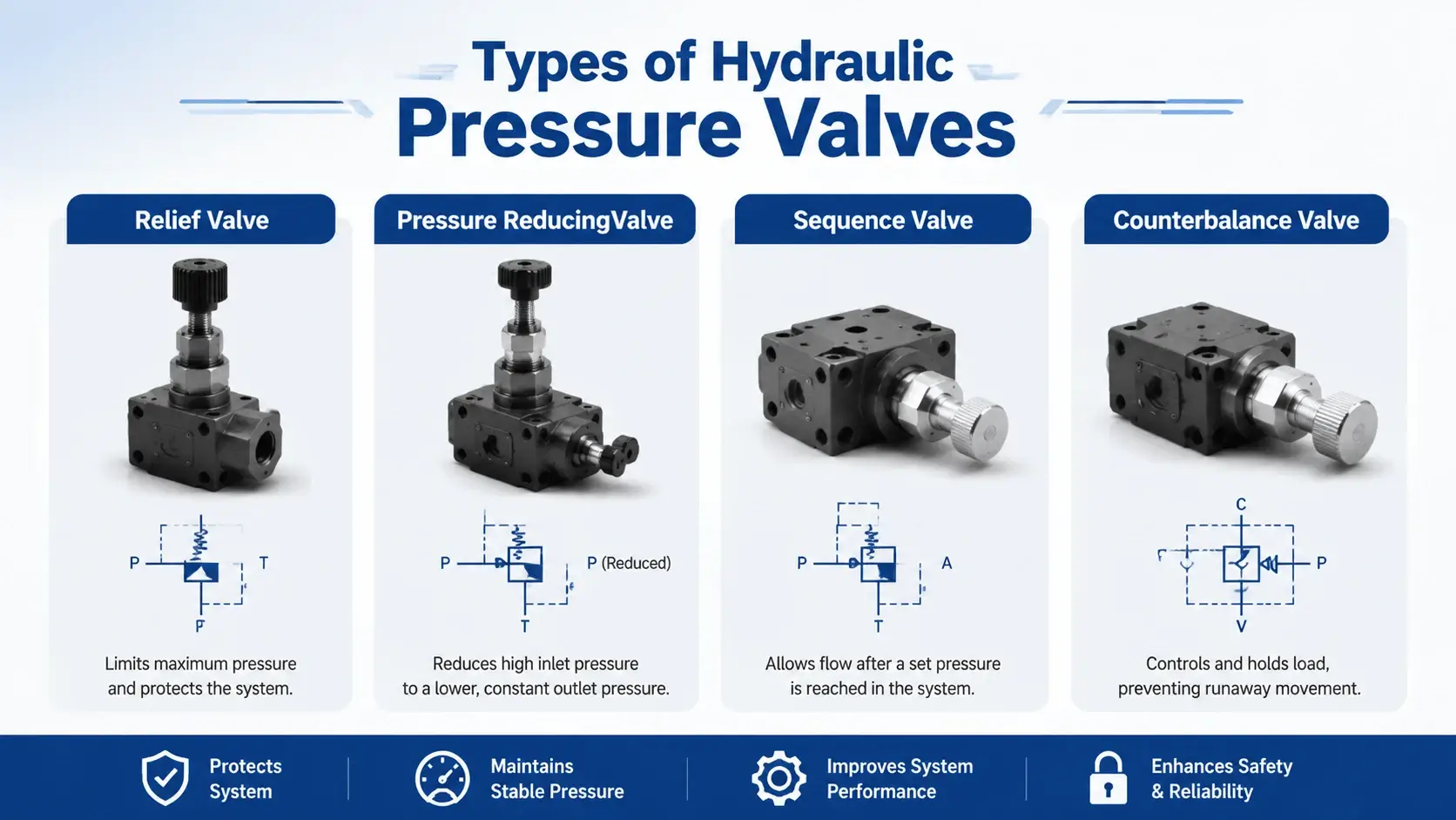
Engineers group these devices into four main categories. Each serves a distinct purpose in a circuit.
| Valve Type | Normal State | Primary Function | Typical Location |
|---|---|---|---|
Relief Valve |
Closed |
Overpressure protection |
Pump outlet, manifold inlet |
Pressure Reducing Valve |
Open |
Downstream regulation |
Sub-circuit inlet |
Sequence Valve |
Closed |
Circuit sequencing |
Branch line |
Counterbalance Valve |
Closed |
Load holding / motion control |
Cylinder or motor return |
Selecting the wrong type leads to poor performance even if the pressure rating matches. A pressure valve must match both its pressure band and its functional role.
Relief Valves: The First Line of Defense
Relief valves protect hydraulic systems from overpressure damage. They stay closed until system pressure hits the cracking point. At that moment, the poppet lifts off its seat and excess fluid routes back to the tank.
Two designs dominate the market. Direct-acting relief valves use a single spring-and-poppet mechanism. They respond fast and cost less, making them ideal for low-flow safety applications under 40 L/min.
Pilot-operated relief valves add a small pilot stage. The main stage opens only when pilot pressure builds enough to overcome a light main spring. This design handles flows above 100 L/min with minimal pressure override.
Pressure override matters more than many engineers realize. A direct-acting valve might crack at 200 bar but not pass full flow until 230 bar. That 15% override wastes energy as heat. Pilot-operated units typically hold override under 5%. If your system runs continuously near its set point, the lower override of a pilot-operated design pays off in cooler oil and longer pump life.
Pressure Reducing Valves: Controlling Downstream Pressure
A pressure-reducing valve does the opposite of a relief valve. It maintains lower pressure in a secondary circuit while the main system operates at a higher pressure. The valve stays fully open until the outlet pressure reaches the set value. Then it throttles to limit downstream pressure regardless of inlet fluctuations.
Typical applications include clamp circuits running at 70 bar while the main system delivers 210 bar, or brake circuits that need consistent reduced pressure. The valve here senses outlet pressure through an internal pilot channel. A spring sets the target. If downstream pressure climbs, the spool moves to restrict flow.
One detail catches people out: a reducing valve needs flow to function. With no flow, the inlet and outlet pressures equalize. Designers sometimes add a check valve in parallel so that reverse flow bypasses the reducing element during cylinder retraction.
Sequence Valves: Orchestrating Circuit Operations
Sequence valves ensure one actuator completes its stroke before another starts. They look similar to relief valves externally but include an external drain port and often a separate pilot signal source. The valve stays closed until either the inlet pressure (direct pilot) or a remote pilot signal reaches the set point.
Consider a press application. The clamp cylinder must grip the workpiece before the main ram descends. A sequence valve on the main ram branch blocks flow until clamp pressure hits the preset level. Once that threshold is crossed, the valve opens, and the ram extends.
Drain line routing makes or breaks a sequence valve installation. Backpressure in the drain line adds to the effective set pressure. If the tank line has 5 bar of backpressure and the valve is set for 100 bar, the actual sequencing happens at 105 bar. Always run the drain line directly to the tank with no restrictions when you install a sequence valve.
Counterbalance Valves: Holding Loads Safely
Counterbalance valves prevent loads from running away when a directional valve shifts to lower or extend an actuator. They sit in the return line from a cylinder or motor and maintain a minimum backpressure that opposes the load.
The valve opens only when pilot pressure from the opposite side of the actuator reaches a ratio (typically 3:1 or 4.5:1) of the load pressure.
Over-running loads pose the biggest risk. A vertically mounted cylinder lowering a heavy payload generates enormous pressure on the rod side as gravity pulls it down. Without a counterbalance valve, the load accelerates uncontrollably. The valve here acts as a dynamic brake, modulating flow to match the pump delivery.
Setting the pilot ratio correctly matters. Too low and the valve feels sluggish, causing jerky motion. Too high and it requires excessive pilot pressure, wasting energy and generating heat. Most manufacturers recommend starting at 3:1 for smooth-controlled applications and 4.5:1 for positive locking.
Selecting the Right Pressure Valve
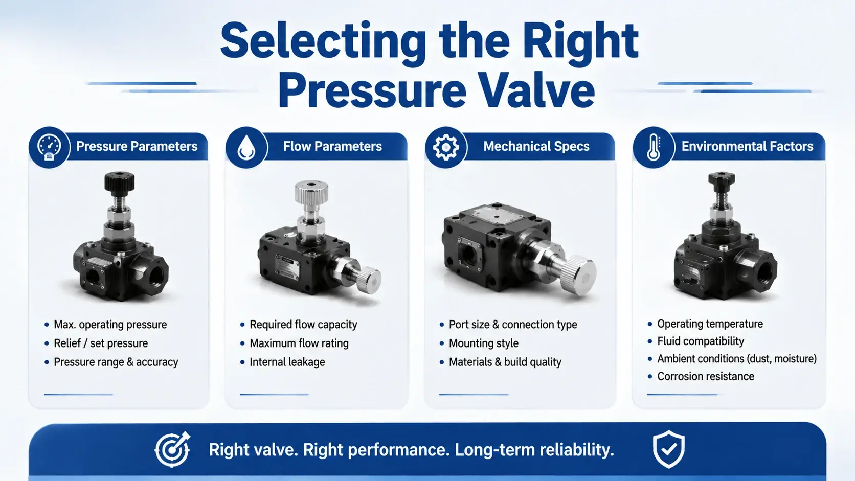
Choosing a pressure valve involves more than matching the pressure rating. Use this checklist on every specification:
Pressure Parameters
- Maximum operating pressure (bar or psi)
- Cracking pressure tolerance (+/- percentage)
- Acceptable pressure override (%)
Flow Parameters
- Minimum and maximum flow rate (L/min)
- Flow range where the valve remains stable
Mechanical Specs
- Mounting pattern (ISO 4401/CETOP, cartridge cavity, threaded)
- Port size and thread standard (SAE J1926, ISO 6149)
- Adjustment range and resolution
Environmental Factors
- Fluid temperature range
- Contamination sensitivity (nominal filtration requirement)
- External load vibration exposure
For most industrial applications below 350 bar and 120 L/min, an ISO 4401 NG10 pilot-operated relief valve offers the best combination of cost, override performance, and availability. Cartridge designs suit compact manifolds where space is limited. Threaded direct-acting units work well for auxiliary circuits and shock protection.
Common Problems and Troubleshooting
Pressure Valve Chatter
Chatter shows up as rapid oscillation of the gauge needle accompanied by noise from the valve. Causes include excessive pressure override, air entrainment in the fluid, or an undersized valve operating near its minimum flow limit. Fix it by switching to a pilot-operated design, bleeding air from the system, or selecting a smaller valve size matched to the actual flow range.
Pressure Drift
If set pressure creeps upward over weeks of operation, check for contamination buildup on the poppet or spool lands. Particulate in the 5–15 micron range wedges between moving parts and prevents full reseating. Clean the valve, inspect the seat for scoring, and verify that system cleanliness meets ISO 4406 18/16/13 or better.
Internal Leakage
Cross-port leakage above 5% of rated flow indicates worn sealing surfaces. In a relief valve, measure tank-line flow with the valve closed and system at 90% of set pressure. Readings over 2–3 L/min for an NG10 valve suggest the poppet or seat needs reconditioning. Replace the element if lapping cannot restore the seal.
Overheating Around the Valve Body
Heat localized at the valve means continuous throttling across a pressure drop. Check whether a reducing valve sees inlet pressure far above its setting, or whether a relief valve cracks slightly due to pump slip flow. Either condition dumps energy as heat. Correct the root cause — resize the valve, adjust the setting, or fix the pump inefficiency — rather than adding cooling capacity.
FAQ
What is a hydraulic pressure valve?
A hydraulic pressure valve is a control device that monitors fluid pressure in a circuit and opens, closes, or throttles in response to maintain a set pressure limit or regulated output. The four main types are relief, reducing, sequence, and counterbalance valves.
How does a hydraulic pressure relief valve work?
A relief valve holds a spring-loaded poppet or spool against a seat. System pressure pushes against an area opposing the spring. When pressure force exceeds spring force, the element lifts and routes excess fluid to the tank. Direct-acting designs respond immediately; pilot-operated designs use a small pilot stage for better control at high flow.
What is the difference between a relief valve and a pressure reducing valve?
A relief valve protects the system upstream by opening to tank when inlet pressure exceeds the set point. A pressure reducing valve regulates pressure downstream by throttling flow to maintain a lower outlet pressure. One guards the pump side; the other protects the actuator side.
When should I use a sequence valve?
Use a sequence valve when one operation must complete before another begins. Clamp-then-press, extend-then-rotate, and lift-then-shift are classic patterns. Ensure the drain line routes directly to tank without restrictions.
How do I adjust a pressure valve?
Loosen the locknut on the adjustment screw. Turn clockwise to raise the set pressure, counterclockwise to lower it. Make adjustments in small increments (10–20 bar at a time) with the system running and a gauge connected. Retighten the locknut once the target pressure stabilizes.
Why does my pressure valve chatter?
Chatter usually stems from one of three causes: pressure override exceeding 15–20% of set pressure, air in the hydraulic fluid, or flow rates falling below the valve’s stable operating range. Switching to a pilot-operated design, bleeding the system, or resizing the valve typically resolves the issue.
Conclusion
A pressure valve determines whether a hydraulic system runs safely, efficiently, and predictably. Pick the wrong type or misadjust the setting and you get overheating, erratic motion, or component failure. Match the valve function to the circuit role — relief for protection, reducing for regulation, sequence for ordering, counterbalance for load control — then verify pressure, flow, and mounting compatibility against the datasheet.
Regular inspection and proper contamination control extend valve life dramatically. Most field failures trace back to dirty oil or incorrect adjustment rather than manufacturing defects. Invest ten minutes per month checking settings and sampling fluid, and your pressure valve will deliver years of reliable service.